Impinger I -–1000 Series Service Manual - International 58
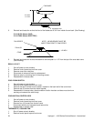
control valve and install the adapter fitting and manometer.
3. Turn on electric power and gas and start-up oven.
4. With oven at full fire, manifold pressure should be (3.5"W.C. NAT/10" W.C. LP).
5. Turn off electric power and gas, replace cover screw, remove manometer and adapter; replace pressure
tap plug.
6. Check pressure tap for gas leaks before closing panel.
7. Close control panel and check system operation.
TEMPERATURE CONTROL VALVE (ROBERT SHAW)
1. Shut off power at main breaker
2. Shut off gas supply.
3. Remove control panel top and front cover.
4. Remove gas control valve (See Above).
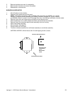
5. Remove the two (2) 3/8" x 16 nuts that hold main orifice bracket to the burner assembly.
6. Remove temperature control valve sensing bulb from oven cavity.
NOTE: It may be necessary to remove conveyor and fingers from oven cavity.
7. Remove piping from old temperature control valve.
8. Reassemble in reverse order, be sure the sensing bulb is properly placed in the oven
cavity. The sensing bulb is properly placed in the oven cavity when it is placed in
the spring holder and positioned with the 5 1/2" of the bulb to the left of the spring holder.
NOTE: The bypass screw should be adjusted all the way in.
SOLENOID VALVE
1. Shut off power at main breaker.
2. Shut off gas supply.
3. Remove control panel top and front cover.
4. Remove gas control valve (See "GAS CONTROL VALVE").
5. Disconnect wires from solenoid valve.
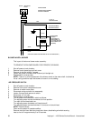
6. Remove two (2) 3/8" x 16 hex nuts that hold main orifice bracket in place.
7. Remove solenoid valve assembly.
8. Remove piping from solenoid valve.
9. Reassemble in reverse order.
TEMPERATURE CONTROL BOARD
Gas Ovens
1. Shut off power at main breaker.
2. Remove control panel top and front cover.
3. Remove relay box cover.
4. Disconnect wiring from temperature control board.
5. Make note of wire number and location for reinstallation.
6. Reassemble in reverse order.
Electric Ovens
1. Shut off power at main breaker.
2. Remove control panel top and front cover.
3. Disconnect wiring from temperature control board.
4. Make note of wire numbers and location for reinstallation.
5. Reassemble in reverse order.
TEMPERATURE CONTROL POTENTIOMETER – REPLACEMENT
1. Remove control panel top and front cover.
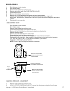
2. Remove one screw from control knob guard and move guard to one side.
3. Remove knob and locknut on control pot. shaft and push out.
4. Remove three (3) wires from temperature control board. Note wire numbers and location.
5. Reassemble in reverse order.


