Impinger I -–1000 Series Service Manual - International 9
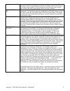
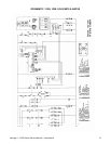
oven start and cool down relay. Its normally open contacts close, supplying 220 VAC
to the Burner Switch and enabling the 20-minute Time Delay module. The 20-minute
Time Delay module supplies 120 VAC to the oven fan motor relay, these normally
open contacts now close, supplying 220 VAC to the Oven Fan Motor.
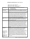
TRANSFORMER(12.6V
AC)
Upon closure of the Fan Switch, 120 VAC is supplied to the primary of the 12.6 VAC
Transformer. The Transformer steps the voltage down to 12.6 VAC (normally 13 to 14
VAC) with a center tap, and supplies power to the Time/Temp Display. The voltage
from each leg of the Transformer's secondary to the center tap should be one half of
the secondary voltage.
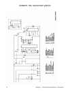
BURNER CIRCUIT Closing the normally open burner switch supplies 220 VAC through the oven air
pressure switch, the gas inlet pressure switch, the normally closed high limit
thermostat (opens at 368°C) to the ignition control. The combustion motor is now
energized. The normally open burner blower air pressure switch closes upon sensing
air pressure. After a pre-purge period of 30-60 seconds, the main gas valve and the
spark generator are energized. Ignition should now occur. After proving the pilot
flame, and a 30 second delay, the gas control relay and the burner indicator lamp are
energized.
TEMPERATURE
CONTROL
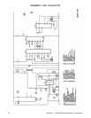
Closing the Fan Switch supplies (through the Step Down Transformer) 120 VAC to
the Temperature Control Board. The Temperature Potentiometer is adjusted to
desired temperature. The Thermocouple will provide varying millivolts to the
Temperature Controller. The Temperature Controller supplies 120 VAC to the
Solenoid Valve at intermittent intervals to maintain desired temperature. (An
electronic flame monitor proves main flame operation in the 1033-1034 models)
CONVEYOR DRIVE Closing the Oven Fan Switch supplies 120 VAC, through the Power Transformer, to
the normally open Conveyor Switch. Closing the Conveyor Switch supplies 120 VAC,
through a 3 AMP Fuse, to the primary of the Conveyor Control Transformer. The
secondary of this Transformer supplies 10 VAC and 29 VAC to the Conveyor Control.
The conveyor control supplies voltage pulses to the Conveyor Control. The Conveyor
Control Potentiometer varies the frequency of these pulses. The motor speed will
increase or decrease, as the frequency of the pulses increase or decrease
respectively.
TIME TEMP DISPLAY Closing the Oven Fan Switch supplies 120 VAC, through the Power Transformer, to
the primary of the Time/Temp. Transformer. The secondary output of the
Transformers, 12.5 to 15 VAC with a center tap, is supplies to terminals 1, 2, and of
the Time/Temp. Display. The display works on a balanced input, and the center tap
voltage to each leg must be 1/2 the total reading.The speed side of the Time/Temp.
Display is supplied, by the Conveyor Control, with the frequency of the pulses to the
Conveyor Motor. This frequency is converted by the Time/Temp. Display into a read
out of minutes and seconds. NOTE: The Conveyor Control uses a sensor and
magnet, mounted on the Conveyor Motor that senses when the motor is not turning. If
the motor is not turning, the Time/Temp Display will show --:-- in the window. The
temperature portion of the display uses a Thermistor Probe to sense oven
temperature. The Thermistor outputs a resistance proportional to oven temperature.
This resistance is then converted by the Display into a temperature reading.
OR:
The temperature portion of the display uses a "J" type thermocouple to measure oven
temperature. The thermocouple generates D.C. millivolts proportional to oven
temperature. This millivolt reading is then converted by the display into a temperature
reading.


