


24P/N60250September28,2012
II. MAINTENANCE – MONTHLY
NOTE: When removing the conveyor, refer to Figure 2-12 (in
Section 2, Installation).
A. Check that the oven is cool and the power is disconnected,
as described in the warning at the beginning of this Sec-
tion.
B. Remove the crumb trays from the oven.
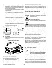
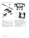
C. Lift the drive end of the conveyor slightly, and push it
forward into the oven. This removes the tension from the
drive chain. Then, remove the drive chain from the conveyor
sprocket.
D. Slide the conveyor out of the oven, folding it as it is removed.
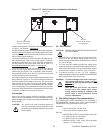
E. Remove the end plugs from the oven. The end plugs are
shown in Figure 1-1 (in Section 1, Description).
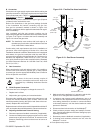
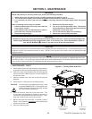
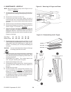
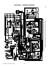
F. Slide the air ngers and blank plates out of the oven, as
shown in Figure 4-2. AS EACH FINGER OR PLATE IS
REMOVED, WRITE A “LOCATION CODE” ON IT WITH A
MARKER to make sure that it can be reinstalled correctly.
Example of markings:
(Top Row) T1 T2 T3 T4 T5 T6
(Bottom Row) B1 B2 B3 B4 B5 B6
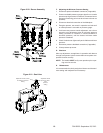
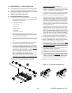
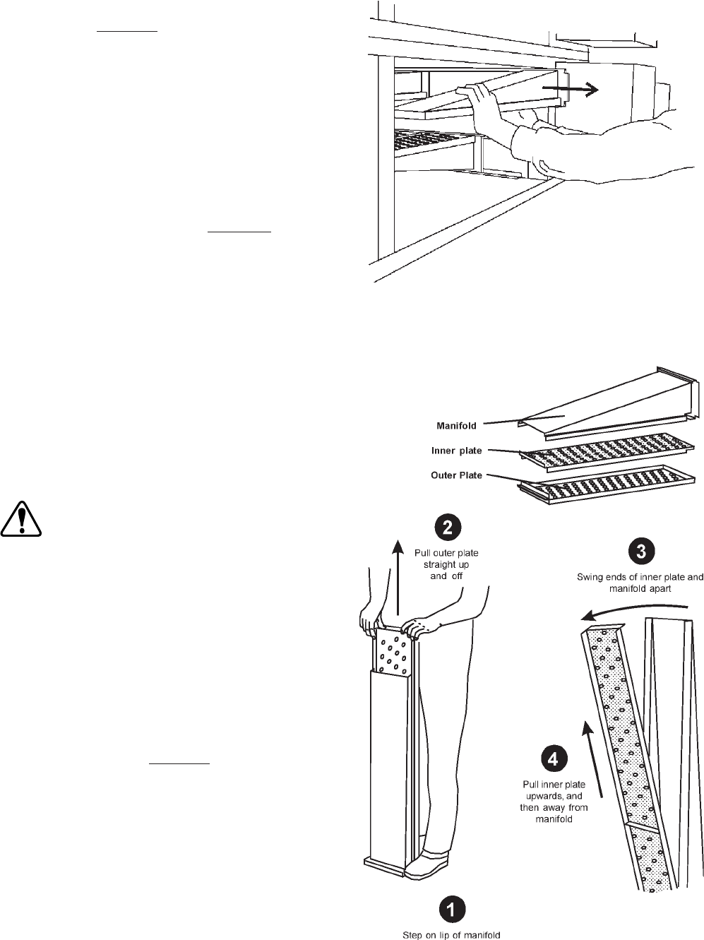
G. Disassemble the air ngers as shown in Figure 4-3. AS
EACH FINGER IS DISASSEMBLED, WRITE THE “LOCA-
TION CODE” FOR THE FINGER ON ALL THREE OF ITS
PIECES. This will help you in correctly reassembling the
air ngers.
CAUTION: Incorrect reassembly of the air ngers will change
the baking properties of the oven.
H. Clean the air nger components and the interior of the baking
chamber using a vacuum cleaner and a damp cloth. Refer
to the boxed warnings at the beginning of this Section for
cleaning precautions.
I. Reassemble the air ngers. Then, replace them in the
oven, using the “location guide” as a guide.
J. Replace the end plugs on the oven.
K. Reassemble the conveyor into the oven. If the drive sprocket
was removed when installing the conveyor, replace it at
this time.
L. Reattach the drive chain.
M. Check the tension of the conveyor belt as shown in Fig-
ure 2-14 (in Section 2, Installation). The belt should lift
between 3 - 4″ (75-100mm). DO NOT OVERTIGHTEN
THE CONVEYOR BELT. If necessary, the belt tension can
be adjusted by turning the conveyor adjustment screws,
located at the idler (right) end of the conveyor.
N. Replace the crumb trays.
Figure 4-2. Removing Air Fingers and Plates
Figure 4-3. Disassembling the Air Fingers