


25 P/N60250September28,2012
III. MAINTENANCE – EVERY 3 MONTHS
A. Check that the oven is cool and the power is disconnected,
as described in the warning at the beginning of this Section.
B. Vacuum both of the blower mounts, and their surrounding
compartments, using a shop vacuum.
C. Tighten all electrical terminal screws.
D. Split Belt Disassembly and Cleaning
1. Refer to Part D, Conveyor Installation, in the Installa-
tion section of this Manual. Then, remove the following
components from the oven:
• Conveyor end stop
• Crumb trays
• Chain cover
• Drive chains
• End plugs
• Conveyor assembly
2. Remove the master links from each conveyor belt.
Then, roll the belts up along the length of the conveyor
to remove them from the frame.
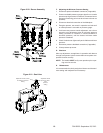
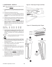
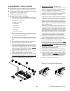
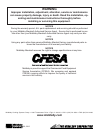
3. Remove the two conveyor adjustment screws from the
idler end of the conveyor frame, as shown in Figure
4-4.
4. Remove the idler shaft assembly from the conveyor.
5. Pull apart the two sections of the idler shaft.
6. Clean the shafts thoroughly using a rag. Then, lubri-
cate both the extended shaft and the interior of the
hollow shaft using a light food-grade lubricant. DO NOT
lubricate the shafts using WD40 or a similar product.
This can cause the shafts to wear rapidly.
7. Before reassembling the shafts into the conveyor
frame, check that they are oriented properly.
8. Reassemble the idler shaft into the conveyor. Make
sure that the bronze washer is in place between the
two sections of the shaft. See Figure 4-4.
9. Replace the conveyor adjustment screws as shown in
Figure 4-4. To allow the conveyor belt to be reinstalled
later, do not tighten the screws at this time.
10. Loosen the set screw on both of the conveyor drive
sprockets. Then, remove the sprockets from the shaft.
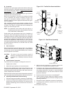
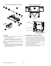
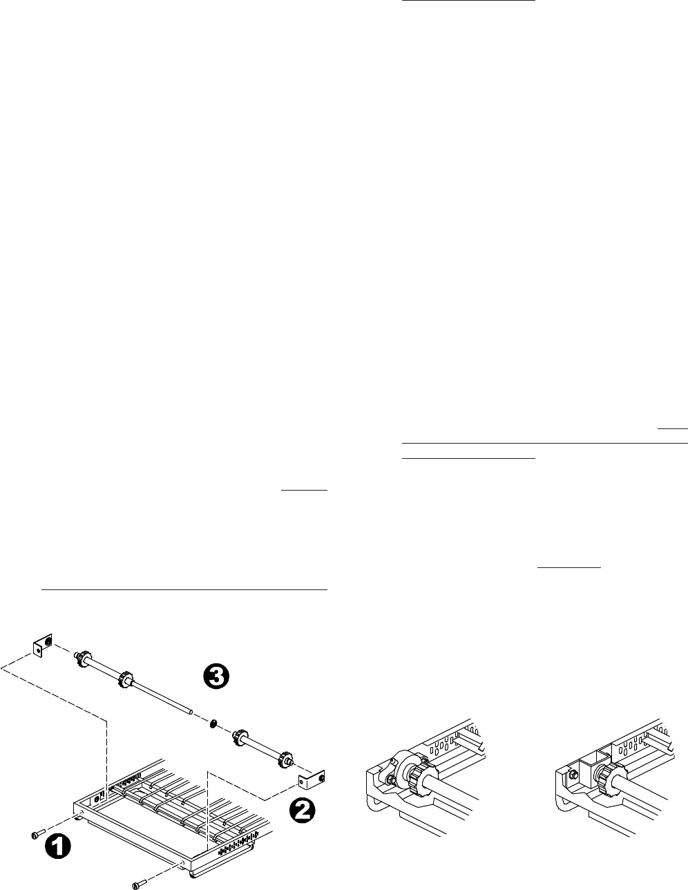
11. Check the conveyor conguration as follows:
High-speed conveyors are equipped with large ange
bearings at both ends of the shaft, as shown in
Figure 4-5. For these conveyors, remove the two
screws that hold each bearing to the conveyor frame.
With the screws removed, lift the end of the shaft at
the front of the oven, and pull the entire assembly free
of the conveyor frame.
Standard conveyors are equipped with bronze bush-
ings mounted on spacers at both ends of the shaft,
as shown in Figure 4-5. For these convey ors, remove
the two screws that hold the bracket to the conveyor
frame. With the screws removed, lift the end of the
shaft at the front of the oven, and pull the entire as-
sembly free of the conveyor frame. The brackets will
be removed along with the drive shaft assembly.
12. Disassemble and lubricate the two sections of the
drive shaft as described for the idler shaft, above.
13. Before reassembling the shafts into the conveyor
frame, check that they are oriented properly.
14. Reassemble the drive shaft into the conveyor. Make
sure that the bronze washer is in place between the
two sections of the shaft. See Figure 4-4.
15. Replace the drive sprockets. Reassemble the belts
and master links onto the conveyor.
16. Reinstall the end plugs and conveyor onto the oven.
17. Reattach the drive chains. Replace the chain cover.
18. Check the tension of the conveyor belt as shown in
Figure 2-14 (in Section 2, Installation). The belt should
lift about 1″ (25mm). If necessary, adjust the belt ten-
sion by turning the conveyor adjustment screws.
19. Replace all components onto the oven.
Figure 4-4. Disassembling the idler shaft
Figure 4-5. Drive shaft congurations