


ENGLISH
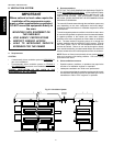
12
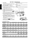
VI. CONVEYOR INSTALLATION
Refer to either Step A or Step B in this section, as appropriate,
to install the conveyor and belt.
A. Installing the Conveyor - All ovens EXCEPT Tandem models
NOTE
Split belt conveyors can only be installed from the end of the oven
with the drive motor.
Single-belt conveyor assemblies may be inserted into either
end of the oven. If it is to be installed from the end of the oven
without the drive motor, the drive sprocket assembly must be
removed.
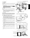
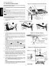
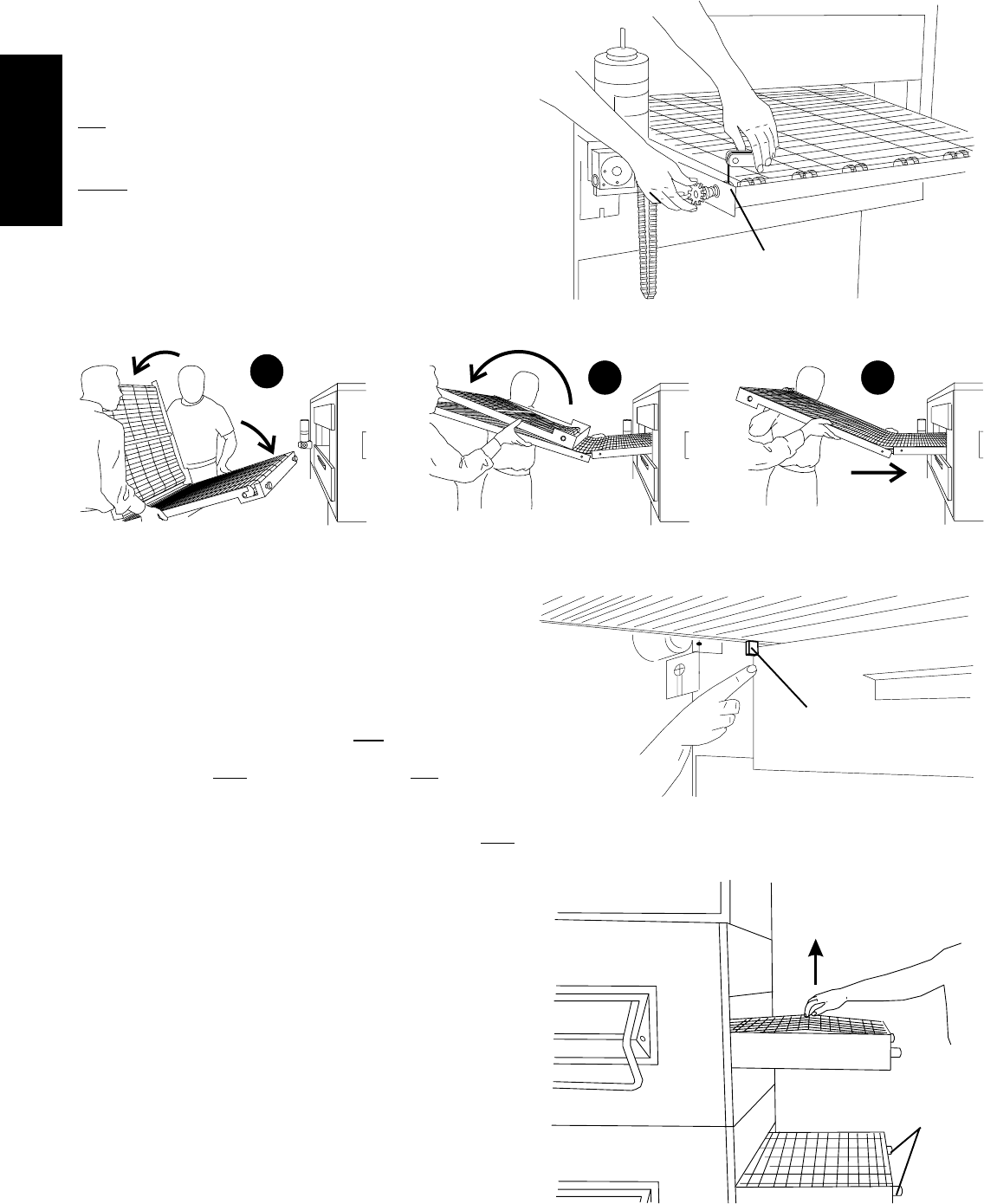
To remove the drive sprocket (if necessary), loosen the set screw
on the conveyor collar as shown in Figure 2-12. Then, pull the
sprocket assembly straight out.
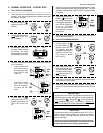
1. Lift the conveyor and position it in the oven as shown in
Figure 2-13.
Figure 2-13 - Inserting the Conveyor
2. Continue moving the conveyor into the oven until the frame
protrudes equally from each end of the oven (about 18"/
457mm).
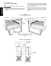
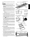
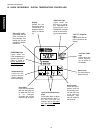
3. Check that the retainers located on the underside of the
conveyor frame rest firmly against the lower end plug, as
shown in Figure 2-14.
NOTE:
PS360EWB ovens have a retainer bracket that extends the
full width of the conveyor frame on
both ends of the frame.
All other ovens have retainer clips as shown in Figure 2-14,
located on the drive (left) side of the frame only.
4. When the conveyor is positioned properly, check for free-
dom of movement of the conveyor belt by pulling it for about
2-3 feet (60 to 90 cm) with your fingers. The conveyor must
move freely.
5. If the drive sprocket was removed when installing the
conveyor, replace it at this time.
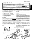
6. Install the drive chain between the conveyor drive sprocket
and the motor sprocket. To install the chain, it will be
necessary to lift the drive end of the conveyor slightly. The
drive motor and sprocket are shown in Figure 2-12.
7. Install the conveyor drive motor cover and tighten its hanger
screw (on the rear wall of the oven).
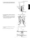
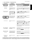
8. Check the tension of the conveyor belt as shown in Figure
2-15. The belt should lift between 3-4" (75-100mm). DO
NOT OVERTIGHTEN THE CONVEYOR BELT.
NOTE:
If necessary, the belt tension can be adjusted by turning the
conveyor adjustment screws, located at the idler (right) end
of the conveyor. See Figure 2-15.
Figure 2-14 - Conveyor retainers
Figure 2-15 - Checking the conveyor tension
3-4"
(75-100mm)
vertical
deflection
Retainers on both ends of
PS360EWB, drive side
only for all other ovens
1
2 3
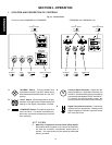
SECTION 2 - INSTALLATION
Figure 2-12 - Removing the Conveyor Drive Sprocket
Loosen conveyor collar
set screw, then pull shaft
straight out
Conveyor
tension
adjustment
screws (idler
end only)