


ENGLISH
13
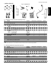
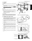
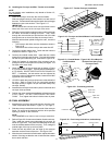
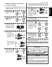
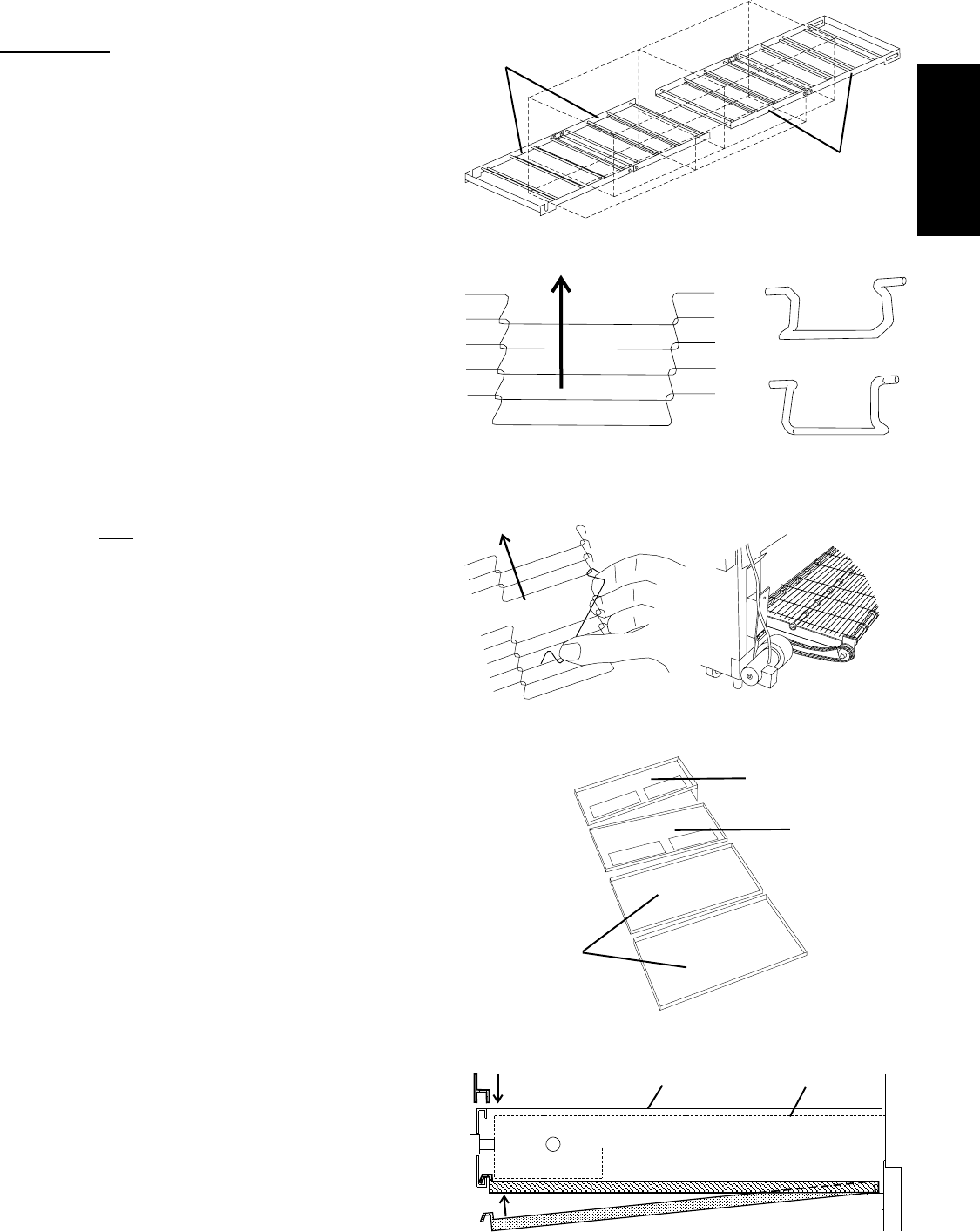
Figure 2-17 - Tandem Conveyor Installation
Hinged
end section
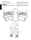
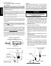
Figure 2-18 - Conveyor and Inside Master Link Orientation
Direction
of travel
Hinged
end section
SECTION 2 - INSTALLATION
B. Installing the Conveyor and Belt - Tandem oven models
NOTE
For non-tandem oven installations, skip ahead to Section VII,
Final Assembly.
1. Insert the conveyor frame into the oven as follows:
Slide one hinged conveyor frame section into each end of
the oven. The two sections butt against each other at the gap
between the two oven sections. See Figure 2-17.
IMPORTANT
Be sure that the drive section of the conveyor frame is at the
same end of the oven as the conveyor drive motor.
2. Slide the conveyor belt through the support rods underneath
the frame, and thread it through the oven. Then, reach
through the oven window and pull the free end of the belt
through the oven so that it lies atop the conveyor frame.
After the belt has been pulled through the oven, check the
following:
The conveyor belt links must be oriented as shown in
Figure 2-18.
The smooth side of the conveyor belt must face UP.
3. Connect the inside master links. Check that the links are
oriented as shown in Figure 2-18.
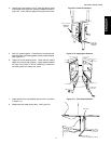
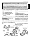
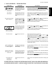
4. Connect the outside master links. Note that the outside
master links have right and left sides. The right-side master
link has an open hook facing you, as shown in Figure 2-19.
5. Check for freedom of movement of the conveyor belt by
pulling it for about 2-3 feet (60 to 90 cm) with your fingers. The
conveyor
must move freely.
6. Check the tension of the conveyor belt as shown in Figure
2-15 (on the previous page). The belt should lift between 3-
4" (75-100mm). DO NOT OVERTIGHTEN THE CONVEYOR
BELT. If necessary, the belt tension can be adjusted by
turning the conveyor adjustment screws, located at the idler
(right) end of the conveyor.
7. LOOSELY attach the conveyor drive motor to the end wall of
the oven. Refer to Figure 2-12 (for ovens with standard
conveyor frames) or Figure 2-20 (for ovens with heavy-duty
conveyor frames).
8. Assemble the conveyor drive chain in place on the motor and
conveyor drive sprockets.
9. Position the motor to adjust the deflection of the drive chain
to 3/4 (19mm). DO NOT OVERTIGHTEN THE DRIVE
CHAIN. Then, tighten the bolts to hold the motor in place.
VII. FINAL ASSEMBLY
1. Assemble the end plugs and motor housing onto the oven.
These components are shown in Figure 1-1 (on Page 1).
2. Slide the conveyor extensions over the ends of the conveyor
frame. Be sure that the extension with the drive sprocket
opening is placed on the drive end.
NOTE
The PS360EWB oven does not use conveyor extensions.
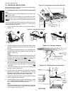
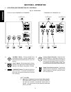
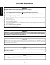
3. Refer to Figure 2-21 for the correct location of each crumb tray.
Then, install the crumb trays underneath the conveyor as
shown in Figure 2-22. First, place the inside edge of the tray
onto the bracket attached to the end plug. Then, swing the
outside edge of the tray up and into place.
4. Press the end stop down over the edge of the conveyor
extension at the exit end of the oven. See Figure 2-22.
5. After the oven is moved to its final location, adjust the bottom
section of the legs so that the oven is level and the casters
do not touch the floor.
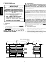
CORRECT
master link
position
Incorrect
master link
position
Figure 2-19 - Outside Master
Link Orientation
Direction
of travel
Figure 2-20 - Drive Motor for
Tandem Oven Heavy-Duty
Conveyor Frame
Figure 2-22 - Crumb trays, extensions, and end stop
Crumb tray
End stop
Conveyor extension Conveyor frame
Figure 2-21 - Crumb tray positions
Upper Oven
(Drive End)
Upper Oven
(Idler End)
Lower Oven