


24
ENGLISH FRANÇAIS ESPAÑOL
page 1 page 25 página 49
Middleby Cooking Systems Group 1400 Toastmaster Drive Elgin, IL 60120 USA (847)741-3300 FAX (847)741-4406
24-Hour Service Hotline: 1-(800)-238-8444
www.middleby.com
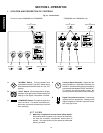
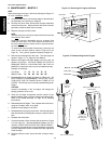
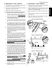
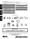
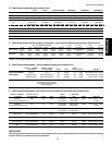
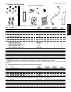
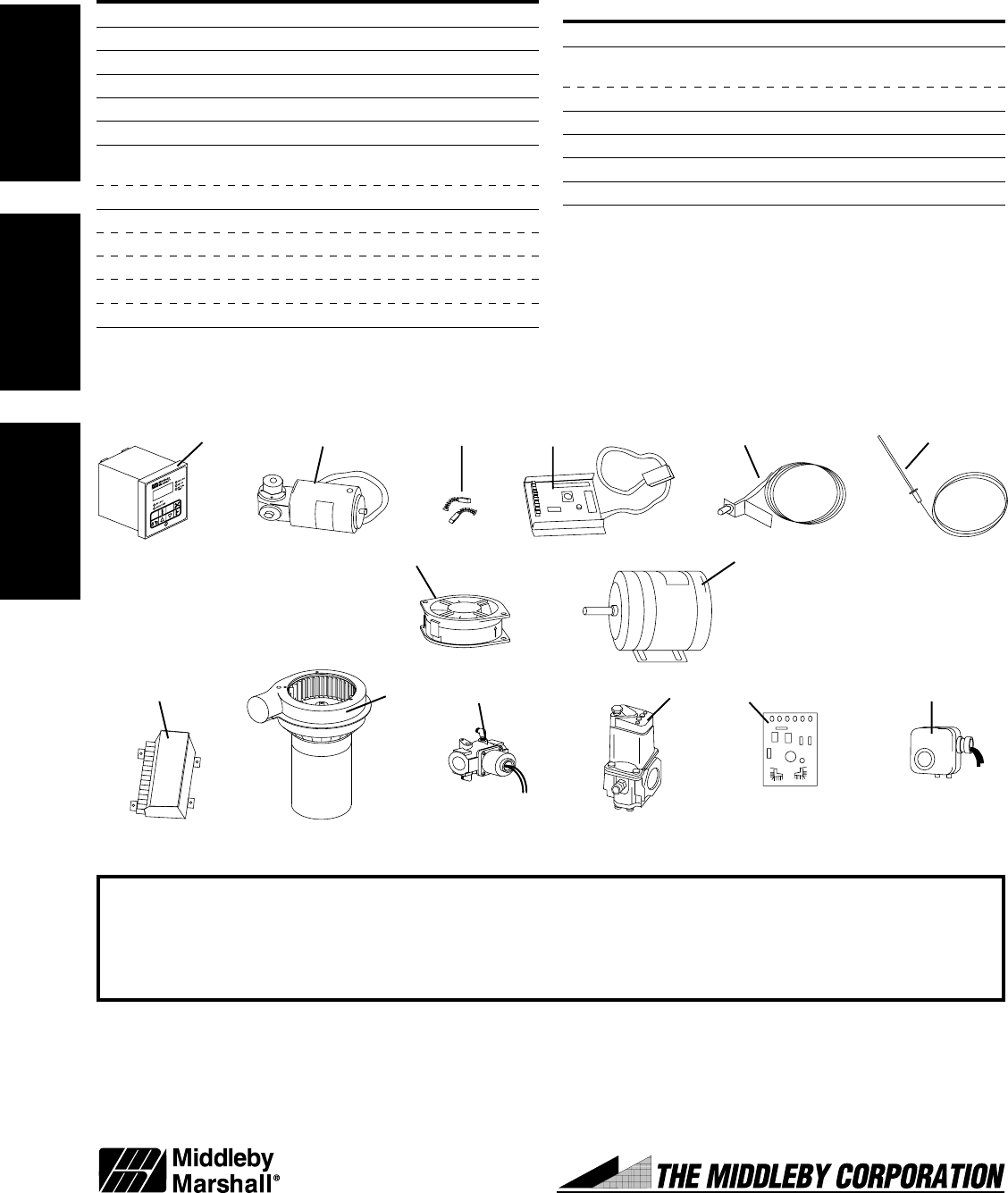
V. KEY SPARE PARTS KIT - Available separately. See Figure 4-9.
A. Key Spare Parts Kit components (all ovens)
Item Description Part Number
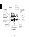
1 1 Kit, Digital Temperature Controller 36939
2 1 Conveyor Drive Motor 27384-0008
3 2 Brushes, Conveyor Drive Motor 22450-0052
4 1 Kit, Conveyor Speed Controller 42810-0133
5 1 Conveyor Control Pickup Assembly 27170-0263
6 1 Thermocouple 33984
7a 1 Cooling Fan (PS310, 314, 360, 360Q, 27392-0002
360S, 360WB)
7b 1 Cooling Fan (PS360EWB, WB70) 36451
8a 1 Blwr Mtr, 1 Ph, 1/3 HP (PS310, 314, 360, 360S) 27381-0023
8b 1 Blower Motor, 3 Ph, 1/3 HP (PS310, 314, 360) 27381-0024
8c 1 Blower Motor, 1 Ph, 1/4 HP (PS360Q) 27381-0054
8d 1 Blower Motor, 1 Ph, 1/2 HP (PS360WB) 27381-0075
8e 1 Blower Motor, 1 Ph, 1 HP (PS360EWB, WB70) 31432
Fig. 4-9 - Key Spare Parts Kit
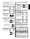
B. Additional Key Spare Parts Kit components for gas
ovens
Item Description Part Number
9 1 Kit, Ignition Module 42810-0114
10a 1 Burner Blower/Motor Assembly 27170-0011
(PS310, 314, 360, 360Q, 360S, 360WB)
10b 1 Burner Blower/Motor Assembly (PS360EWB, WB70) 38811
11 1 Solenoid Valve (All ovens EXCEPT PS360EWB) 28091-0017
12 1 Modulating Valve (PS360EWB) 32570
13 1 Amplifier, Modulating Valve (PS360EWB) 31651
14 1 Air Switch (PS360EWB, WB70) 32102
IMPORTANT
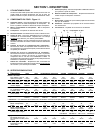
An electrical wiring diagram for the oven is located inside the
machinery compartment or control compartment.
SECTION 4 - MAINTENANCE
12 34 5 6
7
8
91011121314