


ENGLISH
22
II. MAINTENANCE - MONTHLY
NOTE
When removing the conveyor, refer to the drawings on Pages 12-
13 in the Installation section.
A. Check that the oven is cool and the power is disconnected,
as described in the warning on Page 20.
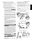
B. Remove the drive motor shroud and conveyor extension
covers from the oven. Disconnect the drive chain from the
sprocket on the drive shaft of the conveyor.
C. Slide the conveyor out of the oven.
NOTE
Split belt conveyors can only be removed from the end of the
oven with the drive motor.
Single-belt conveyor assemblies may be removed from
either end of the oven. If it is to be removed from the end of
the oven without the drive motor, the drive sprocket assem-
bly must be removed.
To remove the drive sprocket (if necessary), loosen the set
screw on the conveyor collar as shown in Figure 2-12 (on
Page 12). Then, pull the sprocket assembly straight out.
D. Remove the end plugs from the oven. The end plugs are
shown in Figure 1-1, on Page 4 of this Manual.
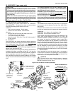
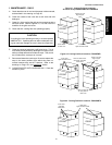
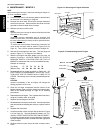
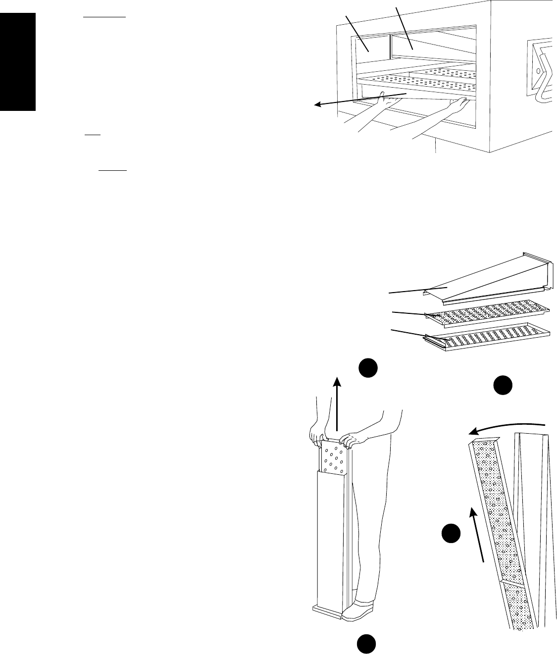
E. Slide the air fingers and blank plates out of the oven, as
shown in Figure 4-4. AS EACH FINGER OR PLATE IS
REMOVED, WRITE A "LOCATION CODE" ON IT WITH A
MARKER to make sure that it can be reinstalled correctly.
Example of markings:
(Top Row) T1 T2 T3 T4 T5 T6
(Bottom Row) B1 B2 B3 B4 B5 B6
F. Disassemble the air fingers as shown in Figure 4-5. AS
EACH FINGER IS DISASSEMBLED, WRITE THE "LOCA-
TION CODE" FOR THE FINGER ON ALL THREE OF ITS
PIECES. This will help you in correctly reassembling the air
fingers.
CAUTION
Incorrect reassembly of the air fingers will change the
baking properties of the oven.
G. Clean the air finger components and the interior of the
baking chamber using a vacuum cleaner and a damp cloth.
Refer to the boxed warnings on Page 20 for cleaning
precautions.
H. Reassemble the air fingers. Then, replace them in the oven,
using the "location code" as a guide.
I. Replace the end plugs on the oven.
J. Reassemble the conveyor into the oven. If the drive sprocket
was removed when installing the conveyor, replace it at this
time.
K. Reattach the drive chain.
L. Check the tension of the conveyor belt as shown in Figure
2-15 (on Page 12). The belt should lift between 3-4" (75-
100mm). DO NOT OVERTIGHTEN THE CONVEYOR BELT.
If necessary, the belt tension can be adjusted by turning the
conveyor adjustment screws, located at the idler (right) end
of the conveyor.
M. Replace the drive motor shroud and the conveyor exten-
sions.
Figure 4-4 - Removing Air Fingers and Plates
Figure 4-5 - Disassembling the Air Fingers
Blank Plate
Air Finger
Pull outer plate
straight up
and off
Manifold
Inner plate
Outer Plate
2
Step on lip of manifold
1
Swing ends of inner plate and
manifold apart
3
Pull inner plate
upwards, and
then away from
manifold
4
SECTION 4 - MAINTENANCE