Technical Information
G600 & G800 Electronic Dishwashers
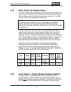
4.19 Drain Pump, Circulation Pump
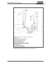
The Drain Pump (M8) is located below the cabinet and connects to the
right / front of the Sump. The Pump removes the wash water through
the Non-Return Valve and Drain Hose to the on-site drain. The Drain
Pump is controlled / powered by the electronic.
Note
If the on-site drain is below the level of the guides for the bottom
basket, the drain must be vented to prevent siphoning. See the
appropriate operating/ installation instructions or call Technical Support
for assistance.
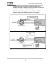
During dishwashing, the Circulation Pump (M6) takes in the wash
water from the side of the Sump through the Microfine Filter and the
Large Surface Area Filter and pumps it to the Spray Arms. During
drainage, the Drain Pump removes water out from below the Microfine
Filter. This change of direction in the water flow assist in flushing out
any residues that may have been retained within the Filter. Water
passing through the Non-Return Valve and then to the on-site drain.
A Bimetallic Switch is integrated in the Circulation Pump Motor
Windings and serves as a safety cut-off should the temperature
exceed 150°C (302°F). After a cooling-down phase, which can be
between 10 min - 1 hour the Switch resets automatically. If the Switch
is faulty, the Motor Assembly must be exchanged.
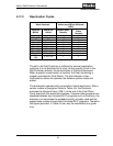
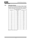
Type Voltage
Rated
Power
Pump
Pressure
Flow Rate
Maximum
Head
Height
Maximum
Hose
Length
(Meters)
Circulation
Pump
120 VAC 120 W 3.6 psi
18.2
gallons /
minute
- -
Drain
Pump
120 VAC 65 W -
4.2 gallons
/ minute
39 inches 13 feet
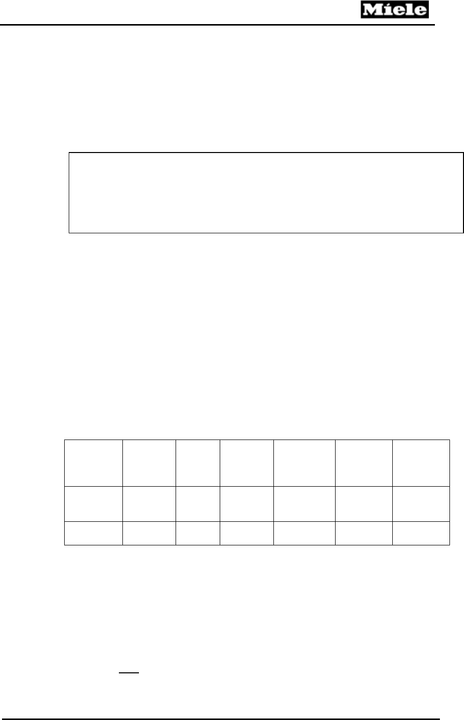
Table 4-7: Circulation and Drain Pump Data
4.20 Level Switch – Heater (Heater Pressure Switch)
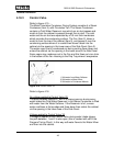
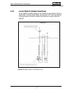
The Level Switch – Heating (Heater Pressure Switch) (B1/10) is
located directly on the Circulation Pump and actuates when water is
present and circulating (producing pressure). The switch is monitored
by the Electronic and is electrically in series with the Heater Relay.
49


