6
Wiring
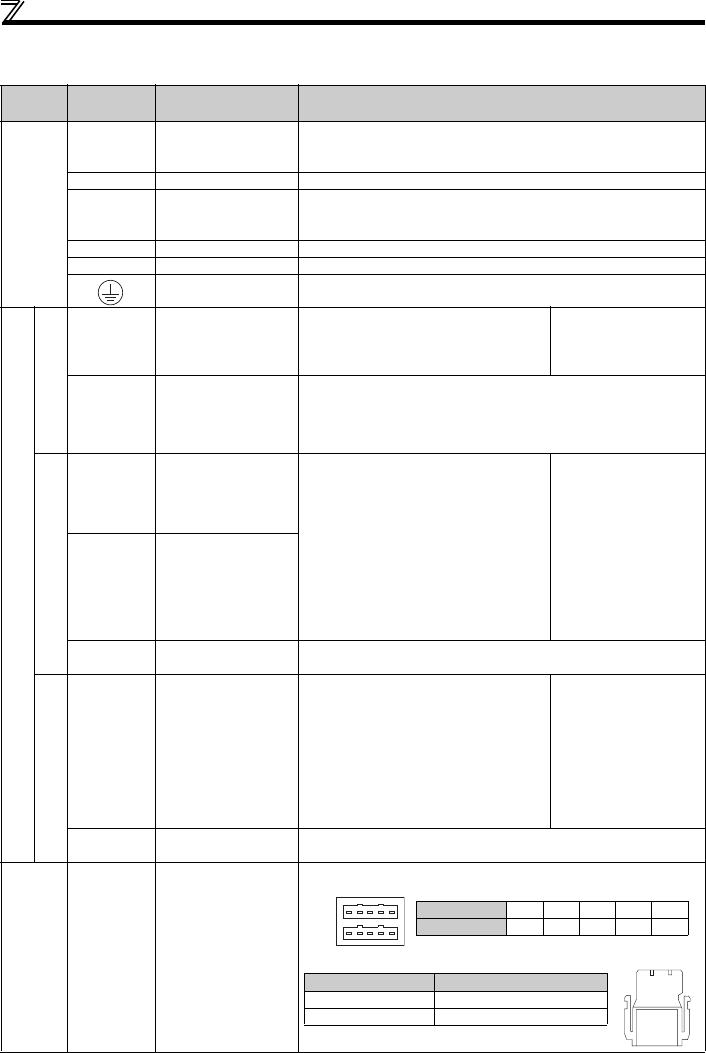
2.3.2 Terminal specifications
Type
Terminal
Symbol
Terminal Name Description
Main circuit
R/L1,
S/L2,
T/L3 *
AC power input
Connect to the commercial power supply.
* When using single-phase power input, terminals are R/L1 and S/L2.
U, V, W Inverter output Connect a three-phase squirrel-cage motor.
P/+, PR Brake resistor connection
Connect a brake resistor (FR-ABR, MRS type, MYS type) across terminals P/+
and PR.
(The brake resistor cannot be connected to the 0.1K or 0.2K.)
P/+, N/- Brake unit connection Connect the brake unit (FR-BU2).
P/+, P1 DC reactor connection Remove the jumper across terminals P/+ and P1 and connect a DC reactor.
Earth (Ground) For earthing (grounding) the inverter chassis. Must be earthed (grounded).
Control circuit
24V external power supply
+24
24V external power
supply
Even when the main circuit power supply is
OFF, CC-Link communication continues with the
input from the 24V external power supply.
Input voltage
23.5 to 26.5VDC
Input current
0.7A or less
SD
24V external power
supply common terminal
Common terminal for the terminal +24
Safety stop function
S1
Safety stop input
(Channel 1)
Terminal S1/S2 are safety stop signals for use
with in conjunction with an approved external
safety unit. Both terminal S1/S2 must be used in
dual channel form. Inverter output is shutoff
depending on shorting/opening between S1 and
PC, S2 and PC.
In the initial status, terminal S1 and S2 are
shorted with terminal PC by shorting wire.
Remove the shorting wire and connect the
safety relay module when using the safety stop
function.
Input resistance 4.7kΩ
Voltage when contacts are
open
21 to 26VDC
When contacts are short-
circuited
4 to 6mADC
S2
Safety stop input
(Channel 2)
PC
Safety stop input terminal
common
Common terminal for safety stop input terminals S1 and S2.
Open collector
Y0
Open collector output Y0
(Inverter running)
Switched low when the inverter output
frequency is equal to or higher than the starting
frequency (initial value 0.5Hz). Switched high
during stop or DC injection brake operation.
(Low indicates that the open collector output
transistor is ON (conducts). High indicates that
the transistor is OFF (does not conduct).)
Use Pr.190 RX2 (terminal Y0) function selection to
change the function assigned to the terminal.
Permissible load 24VDC
(maximum 27VDC) 0.1A
(a voltage drop is 3.4V
maximum when the signal is
ON)
SE
Open collector output
common
Common terminal of terminal Y0.
CC-Link
CONA
CONB
CC-Link communication
connector
Pin arrangement
One-touch connector for CC-Link communication
CONA
CONB
15324
Pin number 54321
Signal name SLD NC DG DB DA
Model name Manufacturer
A6CON-L5P Mitsubishi Electric Corporation
35505-6000-B0M GF Sumitomo 3M Limited


