


11
W415-0158 / E / 02.19.04
FOR SAFE AND PROPER OPERAFOR SAFE AND PROPER OPERA
FOR SAFE AND PROPER OPERAFOR SAFE AND PROPER OPERA
FOR SAFE AND PROPER OPERA
TION OF THETION OF THE
TION OF THETION OF THE
TION OF THE
STST
STST
ST
OO
OO
O
VE, FOLLVE, FOLL
VE, FOLLVE, FOLL
VE, FOLL
OO
OO
O
W THE VENTING INSTRW THE VENTING INSTR
W THE VENTING INSTRW THE VENTING INSTR
W THE VENTING INSTR
UCTIONSUCTIONS
UCTIONSUCTIONS
UCTIONS
EXAEXA
EXAEXA
EXA
CTLCTL
CTLCTL
CTL
YY
YY
Y
..
..
.
FOR HORIZONTFOR HORIZONT
FOR HORIZONTFOR HORIZONT
FOR HORIZONT
AL RAL R
AL RAL R
AL R
UNSUNS
UNSUNS
UNS
, BO, BO
, BO, BO
, BO
TH WTH W
TH WTH W
TH W
OLF STEEL ANDOLF STEEL AND
OLF STEEL ANDOLF STEEL AND
OLF STEEL AND
SIMPSON DURA-VENT VENTING COMPONENTS MASIMPSON DURA-VENT VENTING COMPONENTS MA
SIMPSON DURA-VENT VENTING COMPONENTS MASIMPSON DURA-VENT VENTING COMPONENTS MA
SIMPSON DURA-VENT VENTING COMPONENTS MA
YY
YY
Y
HAHA
HAHA
HA
VE A 0" RISE PER FOOVE A 0" RISE PER FOO
VE A 0" RISE PER FOOVE A 0" RISE PER FOO
VE A 0" RISE PER FOO
TT
TT
T
..
..
.
FOR OPTIMUM PERFORMANCE IT IS RECOM-FOR OPTIMUM PERFORMANCE IT IS RECOM-
FOR OPTIMUM PERFORMANCE IT IS RECOM-FOR OPTIMUM PERFORMANCE IT IS RECOM-
FOR OPTIMUM PERFORMANCE IT IS RECOM-
MENDED THAMENDED THA
MENDED THAMENDED THA
MENDED THA
T ALL HORIZONTT ALL HORIZONT
T ALL HORIZONTT ALL HORIZONT
T ALL HORIZONT
AL RAL R
AL RAL R
AL R
UNS HAUNS HA
UNS HAUNS HA
UNS HA
VE AVE A
VE AVE A
VE A
MINIMUM MINIMUM
MINIMUM MINIMUM
MINIMUM
¼ INCH¼ INCH
¼ INCH¼ INCH
¼ INCH
RISE PER FOO RISE PER FOO
RISE PER FOO RISE PER FOO
RISE PER FOO
TT
TT
T
..
..
.
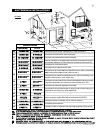
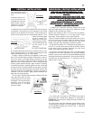
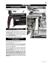
1. Stretch the 4" diameter aluminum flexible liner to the
required length taking into account the additional length
needed for the finished wall surface.
Spacers are attached to the 4" inner flex liner at predeter-
mined intervals to maintain a 1-1/4" air gap to the 7" outer
stove pipe. These spacers must not be removed.
Slip a 4" diameter length of aluminum flexible liner a mini-
mum of 2" over the inner sleeve of the air terminal. Secure
to the sleeve using 3 screws. Seal the joint and screw
heads using the high temperature sealant provided.
2. Slip the first section of 7" diameter stove pipe a mini-
mum of 2" over the outer sleeve of the air terminal. Secure
to the sleeve using 3 screws. Seal the joint and screw
heads using high temperature sealant.
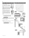
3. Insert the liners through the firestop / vent pipe shield.
Holding the air terminal (lettering in an upright, readable
position), secure to the exterior wall. Make weather tight by
sealing with caulking (not supplied). The air terminal mount-
ing plate may be recessed (up to
3
/
4
" maximum) into the
exterior wall or siding.
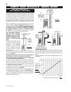
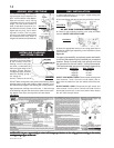
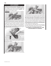
4. If more than one length of liner needs to be used to
reach the stove, couple them together as illustrated in
FIGURE 24. Seal the joints using the same procedure as
described above.
The vent system must be supported approximately every
10 feet along a horizontal run. Use supports or equivalent
non-combustible strapping to maintain the 1" clearance
from combustibles.
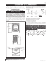
FIGURE 23
FIGURE 24
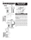
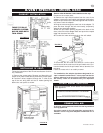
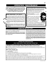
This application occurs
when venting through a
roof.
Installation kits for vari-
ous roof pitches are
available from your Na-
poleon dealer. See Ac-
cessories to order the
specific kit required.
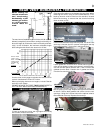
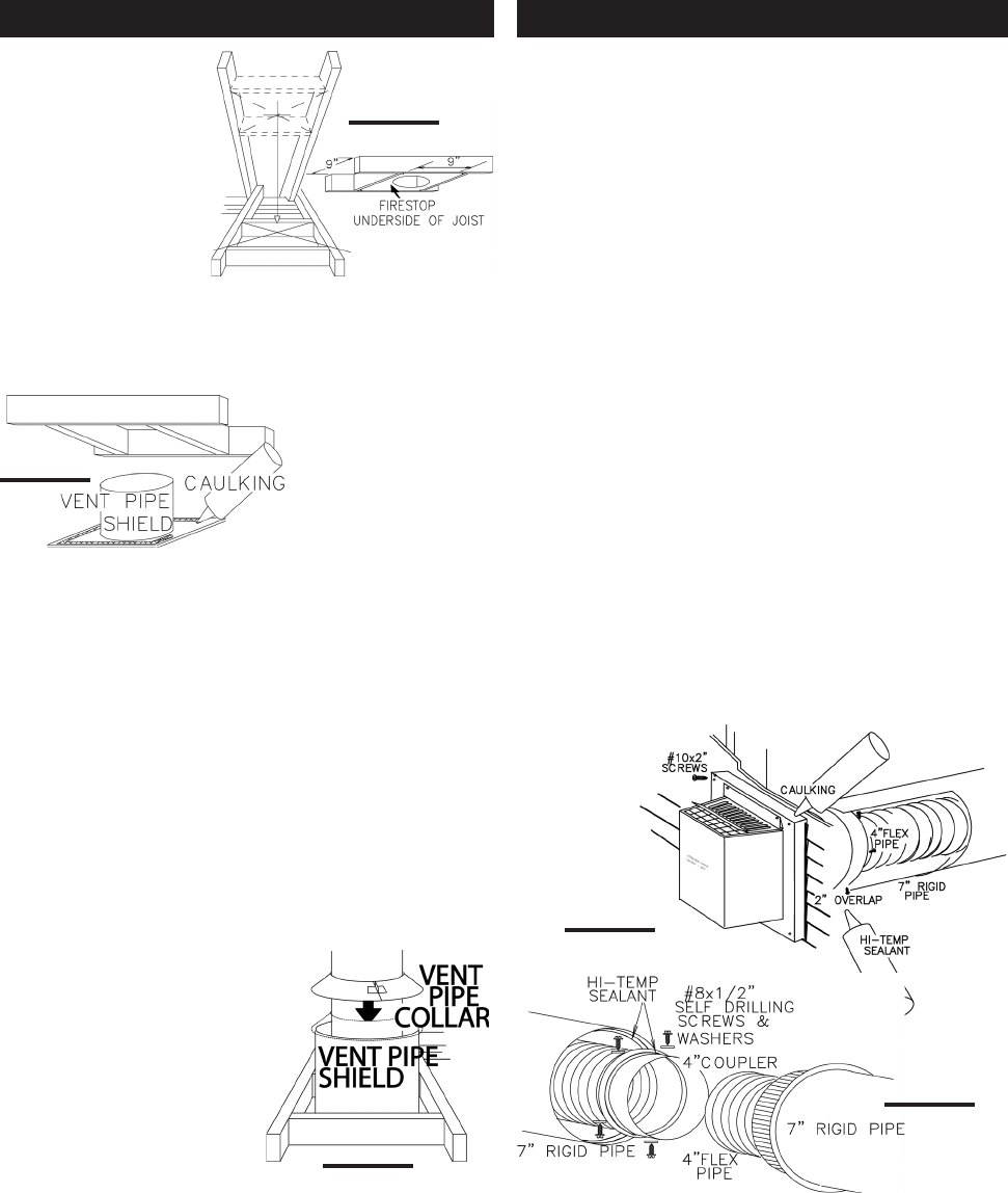
1. Determine the air terminal location and move the stove
into position. Cut and frame 9 inch openings in the ceiling
and the roof to provide the minimum 1 inch clearance be-
tween the stove pipe and any combustible material. Try to
center the exhaust pipe
location midway be-
tween two joist to pre-
vent having to cut them.
Use a plumb bob to line
up the center of the
openings.
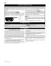
DO NOT FILL THIS SPACE WITH ANY TYPE OF MATERIAL.
A vent pipe shield will prevent any materials such as insu-
lation, from filling up the 1" air space around the pipe. Nail
headers between the joist for extra support.
2. Apply a bead of caulking (not supplied) to the frame-
work or to the Wolf Steel vent pipe shield plate or equiva-
lent (in the case of a finished ceiling), and secure over the
opening in the ceiling. A firestop must be placed on the
bottom of each framed opening in a roof or ceiling that the
venting system passes through. Apply a bead of caulking
all around and place a firestop spacer over the vent shield
to restrict cold air from being drawn into the room or around
the stove. Ensure that both spacer and shield maintain the
required clearance to combustibles. Once the vent pipe is
installed in its final position, apply sealant between the
pipe and the firestop spacer.
3. In the attic, after the pipe has been installed, slide the
vent pipe collar down to cover
up the open end of the shield
and tighten. This will prevent any
materials, such as insulation,
from filling up the 1" air space
around the pipe.
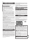
FIGURE 20
FIGURE 21
FIGURE 22
VERTICAL INSTALLATION HORIZONTAL VENTING INSTALLATION