9
W415-0158 / E / 02.19.04
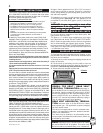
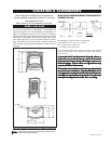
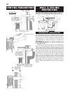
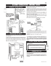
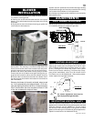
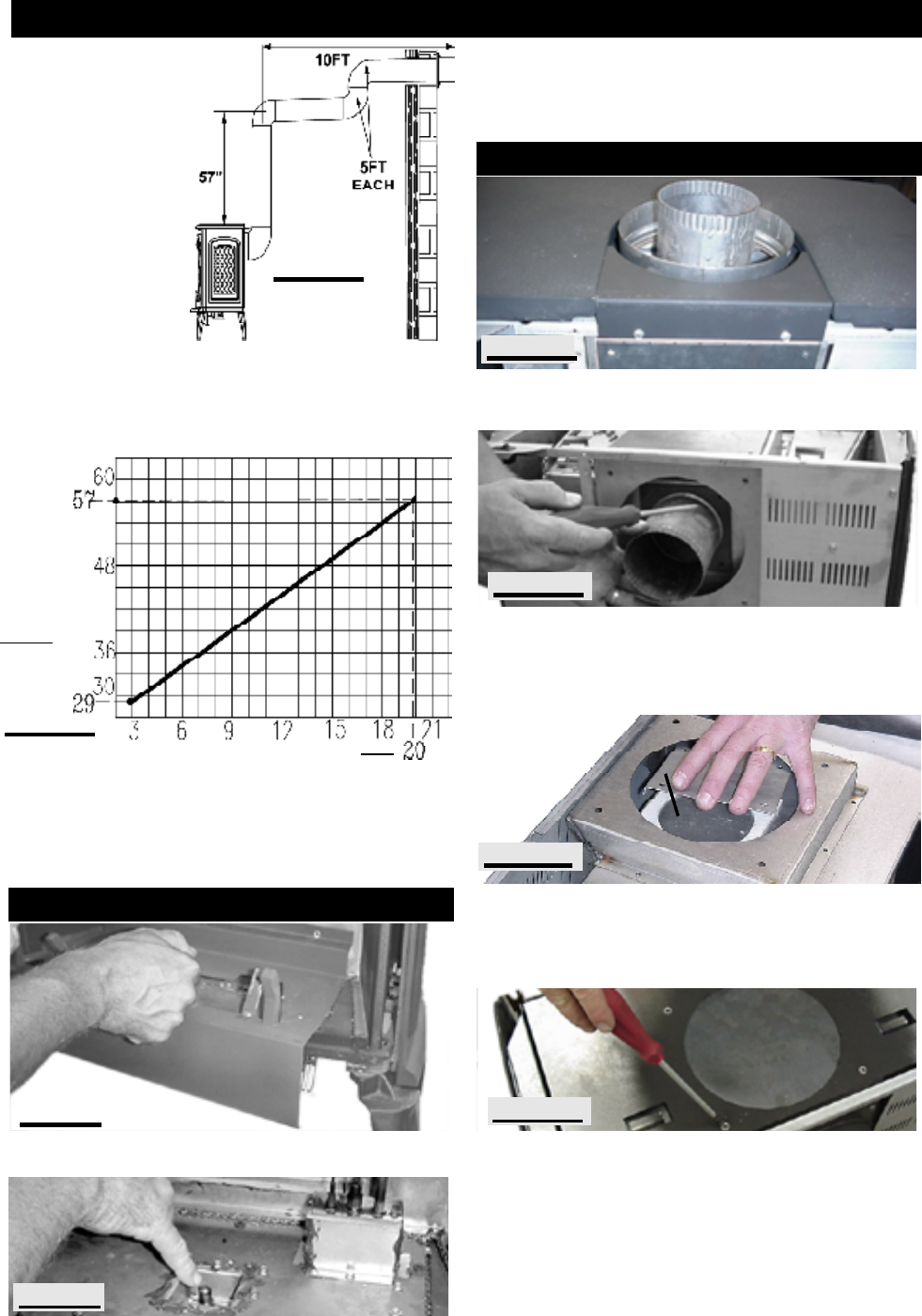
When venting off
the rear of the unit
and terminating
horizontally, a #45
natural gas orifice
or a #55 propane
orifice must be
used.
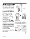
The maximum allowable length is 20 feet. All 90° and 45°
elbows (except the first two when venting horizontally) re-
duce the length by 5 feet each, both horizontally and verti-
cally). In this illustration, the maximum allowable length
after taking the two elbows into account is 10 feet.
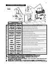
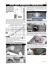
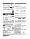
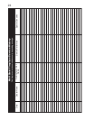
Use the chart on this page to calculate horizontal runs for
vertical rises between 29 and 57 inches.
When calculating maximum run lengths, include 5 feet for
each 90° or 45° elbow.
(DO NOT INCLUDE THE FIRST TWO ELBOWS DIRECTLY
OFF THE UNIT WHEN VENTING HORIZONTALLY.)
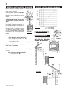
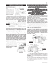
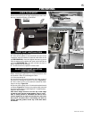
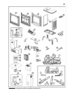
In order to access the orifice, the log support secured by
two screws, must be removed.
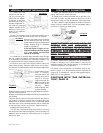
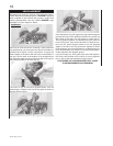
Unscrew and discard the top vent filler plate. Lift off the cast
stove top. Unscrew the four screws holding both the top
heat shield and the 7" flue collar in place and lift off.
Lift the gasket off. Unscrew the 4 screws securing the 4"
collar and its gasket in place and remove it and the knock-
out from the rear panel. Remove the 7" and 4" covers and
gaskets from the back. Position the 4" gasket and cover
over the flue opening in the top.
Secure with 4 screws. Place the 7" gasket and cover over
the air opening in the top. Replace the top heat shield and
re-secure. Secure both gaskets and collars over the rear
openings. Using the 2 screws secure the optional trivet to
the underside of the top. Replace the stove top.
Care should be taken not to damage the gas pipe. When
removing the orifice, using a 9/16" socket wrench, a 7/8"
back-up wrench must be used on the manifold, located
below the housing, to ensure that the aluminum tubing
does not twist or kink.
FIGURE 15
FIGURE 16
STOVE TOP
TOP VENT FILLER PLATE
7" COVER
FIGURE 17a
FIGURE 17b
FIGURE 17d
TOP HEAT SHIELD
REQUIRED
VERTICAL
RISE FROM
FIREPLACE
TO FIRST EL-
BOW IN
INCHES
CALCULATED HORIZONTAL VENT RUN IN FEET
FIGURE 14b
FIGURE 17c
4" COVER
(FLANGE DOWN)
FIGURE 14a
REAR VENT HORIZONTAL TERMINATION
ORIFICE REPLACEMENT
CHANGING A TOP VENT TO A REAR VENT