


14
W415-0158 / E / 02.19.04
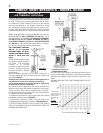
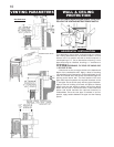
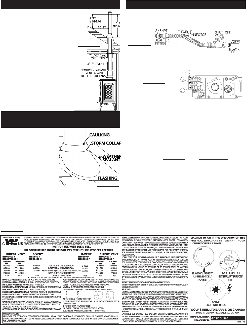
For ease of assembly, a 7" telescop-
ing stove pipe may be installed over
the 4" vent connection of the adapter.
Add vent sections, twist locking
(clockwise) securely, to the required
height. The vent should extend, at
least, 3 feet above its point of con-
tact with the roof and, at least, 2 feet
higher than any wall, roof or build-
ing within 10 feet. (This is a guide-
line only; local venting codes should
be followed which may differ in
height and clearance requirements.)
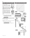
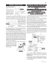
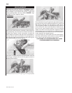
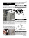
Remove nails from the shin-
gles above and to the sides
of the chimney. Place the
flashing over the vent pipe
and slide it underneath the
sides and upper edge of the
shingles. Ensure that the
vent pipe is properly centered
within the flashing, giving a
3/4" margin all
around. Fasten to the roof on the top and sides.
DO NOT NAIL through the lower portion of the flashing. Make
weather-tight by sealing with caulking. Where possible, cover
the sides and top edges of the flashing with roofing material.
Apply waterproof caulking around the vent, 1" above the top
of the flashing and push the storm collar down into the caulk-
ing. Attach a rain cap to the top of the last vent section.
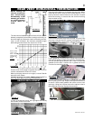
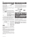
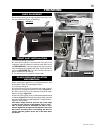
1. Install rigid black pipe, or 1/2" type L copper tubing with
a shut-off valve to the stove.
2. Seal and tighten the gas line securely to the flex connec-
tor.
DO NOT KINK FLEXIBLE CONNECTOR.
3. Check for gas leaks by brushing on a soap and water
solution. DO NOT USE OPEN FLAME.
4. Mark the appropriate boxes on the rating plate label to
indicate the model type depending on the installation (direct
vent or B-vent).
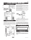
Figure 36.
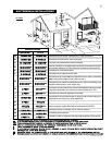
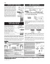
For ease of accessibility, an optional remote wall switch
or millivolt thermostat may be installed in a convenient
location. Route 2 strand solid core millivolt wire from
the gas stove to the wall switch / millivolt thermostat.
The recommended maximum lead length depends on
the wire size: WIRE SIZE MAX. LENGTH
14gauge 100 feet
16gauge 60 feet
18gauge 40 feet
DIRECT VENT MODEL GDS60: Disconnect the existing wires
from terminals 1 and 3 (from the on/off switch) and re-
place with the leads from the wall switch/millivolt thermo-
stat.
B-VENT MODEL GS60: Disconnect the spill switch wire
from terminal 3 on the valve. Connect one lead from the
thermostat to terminal 3 on the valve and the other lead to
the wire from the spill switch.
FIGURE 34
FIGURE 35
FIGURE 33
FIGURE 32
FIGURE 36
INSTINST
INSTINST
INST
ALLER:ALLER:
ALLER:ALLER:
ALLER:
It is y It is y
It is y It is y
It is y
our rour r
our rour r
our r
esponsibesponsib
esponsibesponsib
esponsib
lity to clity to c
lity to clity to c
lity to c
hechec
hechec
hec
k ofk of
k ofk of
k of
ff
ff
f
the a the a
the a the a
the a
pprppr
pprppr
ppr
opriaopria
opriaopria
opria
te bote bo
te bote bo
te bo
x on the rx on the r
x on the rx on the r
x on the r
aa
aa
a
ting plating pla
ting plating pla
ting pla
te accorte accor
te accorte accor
te accor
ding to the model,ding to the model,
ding to the model,ding to the model,
ding to the model,
venting and gas type of the unit.venting and gas type of the unit.
venting and gas type of the unit.venting and gas type of the unit.
venting and gas type of the unit.
GAS INSTALLATION
ADDING VENT SECTIONS
INSTALLING FLASHING
AND STORM COLLAR