


19
W415-0158 / E / 02.19.04
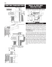
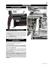
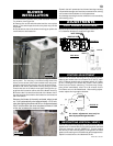
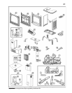
1. Ensure that the access cover plate has been installed.
For location, see Figure 30.
2. Remove the on/off switch bracket and the cover plate
below it. The switch spacers and cover plate may now be
discarded.
3. Decide which side of the blower housing you prefer the
on/off switch to be located on.
4. Remove the 2 screws from the top outer edge of the rear
stove panel. The housing is mounted using these two
holes, as well as two other holes located in the rear panel.
using the same screw holes for one side of the housing.
5. Mount and secure the blower housing using 4 screws.
Ensure that the on/off switch wires pass through the ap-
propriate slot located on either side of the blower housing.
6. Remove the 2 screws from the side of the blower hous-
ing that you want the switch to be located on and resecure
the on/off switch.
Because the blower is thermally activated, when turned
on, it will automatically start approximately 15-30 min-
utes after lighting the stove and will run for approximately
30-45 minutes after the stove has been turned off. Use
of the fan increases the output of heat.
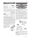
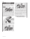
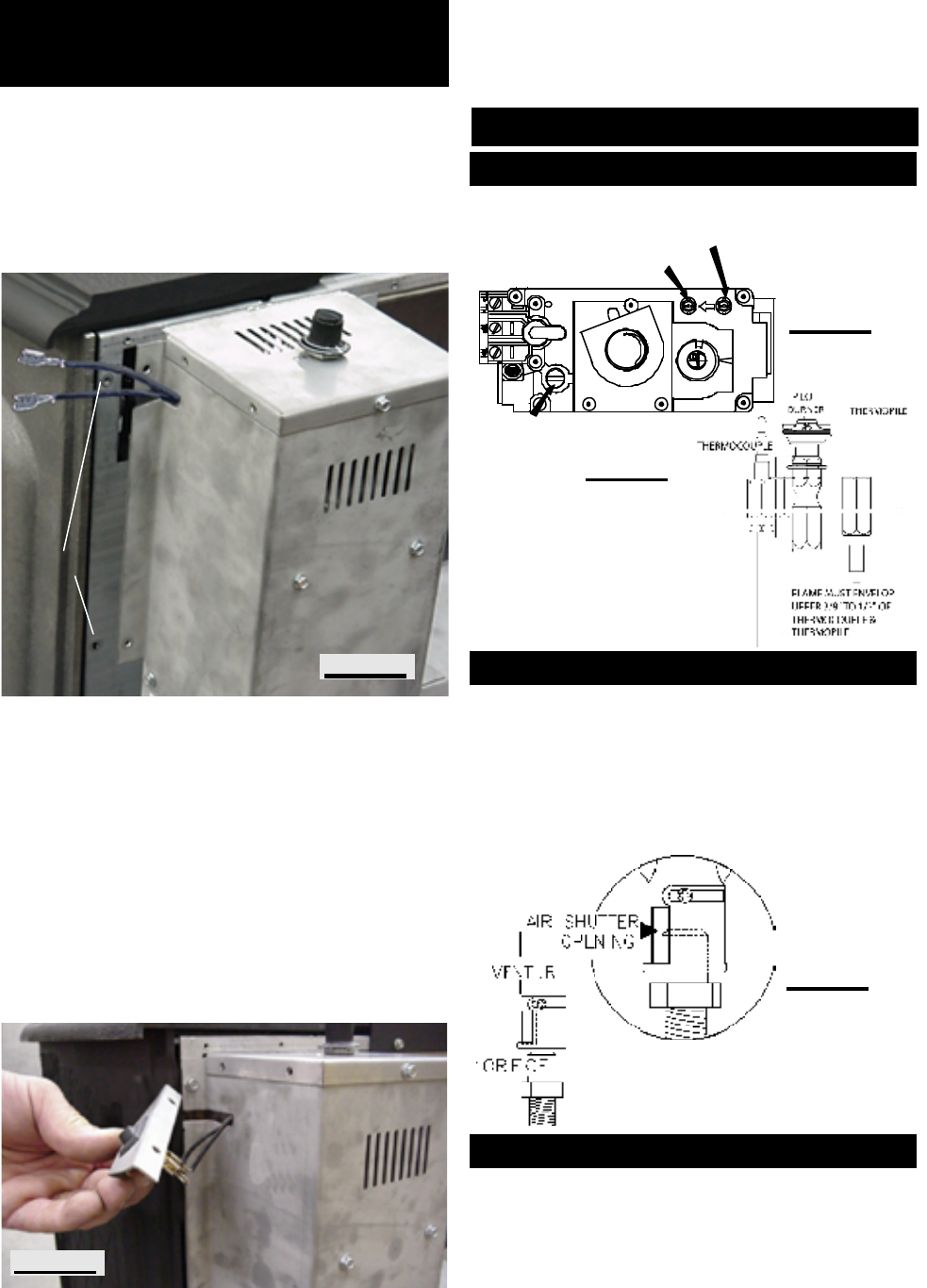
Adjust the pilot screw to provide properly sized flame. Turn
in a clockwise direction to reduce the gas flow.
Remove the 2 screws securing the log support bracket.
Natural gas models have air shutters set to 0.375" open
(3/8"). Propane models have air shutters set to 0.313" open
(5/16"). Closing the air shutter will cause a more yellow
flame, but can lead to carboning. The flame may not ap-
pear yellow immediately; allow 15 to 30 minutes for the
final flame colour to be established. After making adjust-
ments replace the log support bracket.
FIGURE 43
FIGURE 44
P
I
INLET PRESSURE
TAP
P
I
PILOT SCREW
MANIFOLD TAP
L
O
T
N
O
L
O
T
H
I
L
O
F
F
O
Air shutter adjustment must only be
done by a qualified gas installer!
FIGURE 41
FIGURE 45
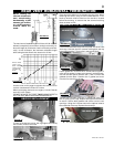
Vertical installations may display a very active flame. If this
appearance is not desirable, the vent exit must be restricted
using the restrictor vent kit, GDSRP-KT. This will reduce
the velocity of the exhaust gases, slowing down the flame
pattern and creating a more traditional gentle appearance.
Specific instructions are included with the kit.
FIGURE 42
SLOT
REMOVED SCREWS
BLOWER
INSTALLATION
ADJUSTMENTS
PILOT BURNER ADJUSTMENT
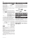
Drywall dust will penetrate into blower bearings causing
irrepairable damage and must be prevented from coming
into contact with the blower or its compartment.
Any damage resulting from this condition is not covered by
the warranty policy.
VENTURI ADJUSTMENT
RESTRICTING VERTICAL VENTS