12
W415-0158 / E / 02.19.04
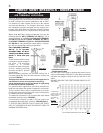
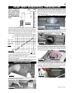
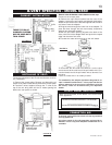
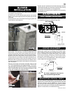
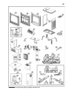
1. Fasten the roof
support to the roof us-
ing the screws pro-
vided. The roof support
is optional. In this case
the venting is to be ad-
equately supported us-
ing either an alternate
method suitable to the
authority having juris-
diction or the optional
roof support.
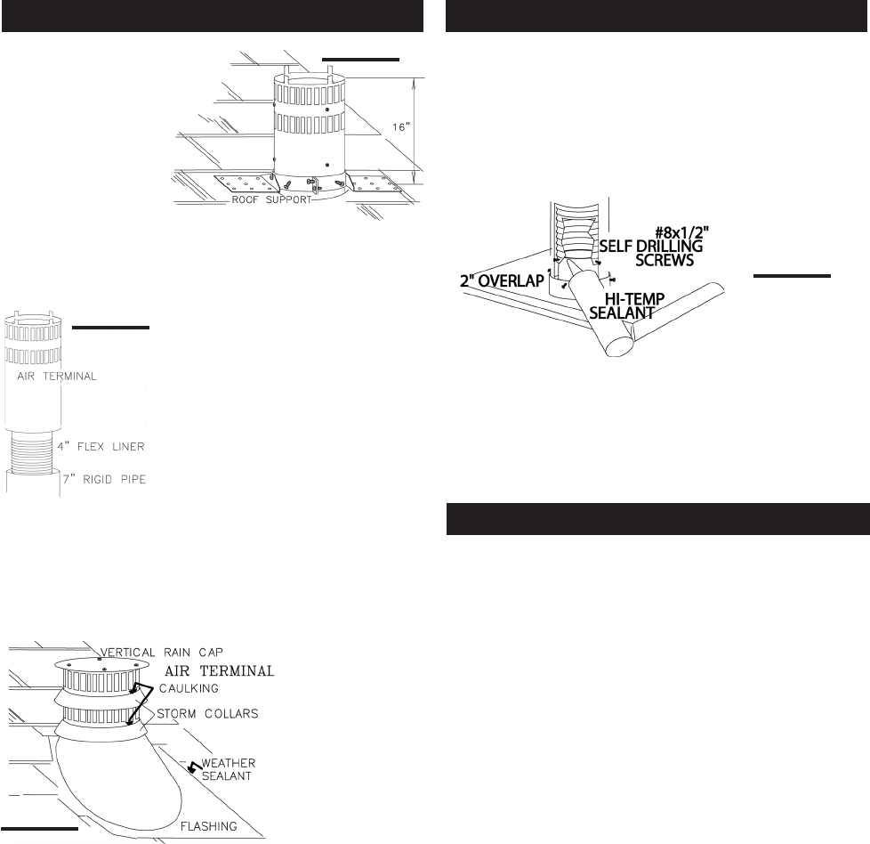
2. Slip a 4" diameter length of aluminum flexible liner a
minimum of 2" over the inner sleeve of the air terminal.
Secure to the sleeve using 3 screws
and flat washers.Seal the joint and
screw heads using high temperature
sealant. Repeat using a 7" diameter
length of rigid piping.
If the attic space is tight, we rec-
ommend adding sufficient lengths
of 7" rigid piping, secured and
sealed as necessary.
3. Thread the air terminal pipe assembly down through
the roof support and attach, ensuring that a minimum 16"
of air terminal will penetrate the roof when fastened. The
air terminal must be located vertically and plumb.
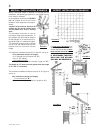
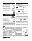
4. Remove nails from the shingles, above and to the
sides of the chimney. Place the flashing over the air termi-
nal and slide it underneath the sides and upper edge of the
shingles.
Ensure that the air ter-
minal is properly
centered within the
flashing, giving a 3/4"
margin all around.
Fasten to the roof. Do
NOT nail through the
lower portion of the
flashing. Make
weather-tight by seal-
ing with caulking.
Where possible, cover the sides and top edges of the flash-
ing with roofing material.
5. Apply a heavy bead of waterproof caulking 2 inches above
the flashing.
Slide the storm collar around the air terminal and down to
the caulking. Tighten to ensure that a weather-tight seal
between the air terminal and the collar is achieved. Attach
the other storm collar centered between the air intake and
air exhaust slots onto the air terminal. Tighten securely.
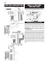
6. Attach the vertical rain cap.
7. In the attic, slide the vent pipe collar down to cover up
the open end of the shield and tighten. This will prevent any
materials, such as insulation, from filling up the 1" air space
around the pipe.
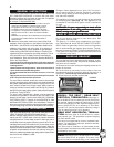
FIGURE 25
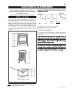
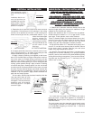
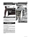
1. Attach the adjustable pipe to the last section of rigid
piping. Secure with screws and seal.
2. Install the 4" aluminum flexible liner to the stove. Se-
cure with 3 screws and flat washers. Seal the joint and
screw holes using the high temperature sealant provided.
3. Run a bead of high temperature sealant around the
inside of the air intake collar. Pull the adjustable pipe a
minimum 2" into the air intake collar.
ENSURE THAENSURE THA
ENSURE THAENSURE THA
ENSURE THA
T THE SEALT THE SEAL
T THE SEALT THE SEAL
T THE SEAL
ANT IS NOANT IS NO
ANT IS NOANT IS NO
ANT IS NO
T VISIBLE ON THET VISIBLE ON THE
T VISIBLE ON THET VISIBLE ON THE
T VISIBLE ON THE
EXTERIOR PIPES ONCE INSTEXTERIOR PIPES ONCE INST
EXTERIOR PIPES ONCE INSTEXTERIOR PIPES ONCE INST
EXTERIOR PIPES ONCE INST
ALLALL
ALLALL
ALL
AA
AA
A
TION ISTION IS
TION ISTION IS
TION IS
COMPLETEDCOMPLETED
COMPLETEDCOMPLETED
COMPLETED
. AN OPTION. AN OPTION
. AN OPTION. AN OPTION
. AN OPTION
AL DECORAAL DECORA
AL DECORAAL DECORA
AL DECORA
TIVE BRASSTIVE BRASS
TIVE BRASSTIVE BRASS
TIVE BRASS
BB
BB
B
AND IS AAND IS A
AND IS AAND IS A
AND IS A
VV
VV
V
AILAIL
AILAIL
AIL
ABLE FOR THIS USE. (STABLE FOR THIS USE. (ST
ABLE FOR THIS USE. (STABLE FOR THIS USE. (ST
ABLE FOR THIS USE. (ST
ANDAND
ANDAND
AND
ARD WITHARD WITH
ARD WITHARD WITH
ARD WITH
A GD175 KIT). IN THE EVENT THAA GD175 KIT). IN THE EVENT THA
A GD175 KIT). IN THE EVENT THAA GD175 KIT). IN THE EVENT THA
A GD175 KIT). IN THE EVENT THA
T THE VENTINGT THE VENTING
T THE VENTINGT THE VENTING
T THE VENTING
MUST BE DISASSEMBLEDMUST BE DISASSEMBLED
MUST BE DISASSEMBLEDMUST BE DISASSEMBLED
MUST BE DISASSEMBLED
, CARE MUST BE T, CARE MUST BE T
, CARE MUST BE T, CARE MUST BE T
, CARE MUST BE T
AKEN TAKEN T
AKEN TAKEN T
AKEN T
OO
OO
O
RESEAL THE VENTING.RESEAL THE VENTING.
RESEAL THE VENTING.RESEAL THE VENTING.
RESEAL THE VENTING.
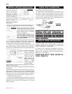
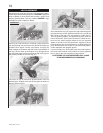
In Canada, mobile home installation may be vented hori-
zontally or vertically. In the United States, it may only be
installed vertically. See "Vertical Venting" or "Horizontal Air
Terminal Installation" for installation.
For mobile home installations, the fireplace must be fas-
tened in place. It is recommended that the fireplace be
secured in all installations. Use the leveling/securing kit,
GDSLL-KT for this purpose.
CONTINUE WITH "GAS INSTALLA-
TION", PAGE 14
FIGURE 26
FIGURE 27
FIGURE 28
VERTICAL VENTING INSTALLATION STOVE VENT CONNECTION
MOBILE HOME INSTALLATION