6
W415-0158 / E / 02.19.04
Use only Wolf Steel or Simpson Dura-Vent Model DV-GS
venting components. Minimum and maximum vent lengths,
for both horizontal and vertical installations, and air termi-
nal locations for either system are set out in this manual
and must be adhered to. For Simpson Dura-Vent, follow
the installation procedure provided with the venting com-
ponents. Both Wolf Steel and Simpson Dura-Vent venting
components may have a 0" rise per foot on horizontal runs.
When using Wolf Steel venting components, use only the
following vent kits: WALL TERMINAL KIT GD175 (7-1/2' of
venting included), or 1/12 TO 7/12 PITCH ROOF TERMINAL
KIT GD110, 8/12 TO 12/12 ROOF TERMINAL KIT GD111,
FLAT ROOF TERMINAL KIT GD112 or STOVE PERISCOPE
KIT GD180 (for wall penetration below grade) in conjunc-
tion with the appropriate venting components.
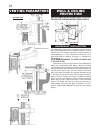
For optimum perform-
ance, it is recom-
mended that all hori-
zontal runs have a mini-
mum ¼ inch rise per
foot.
These vent kits allow for either
horizontal or vertical venting of
the stove. The maximum
number of 4" flexible
connections is two horizontally
or three vertically (excluding
the stove and the air terminal
connections).
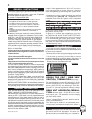
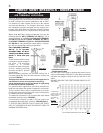
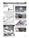
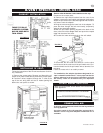
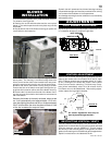
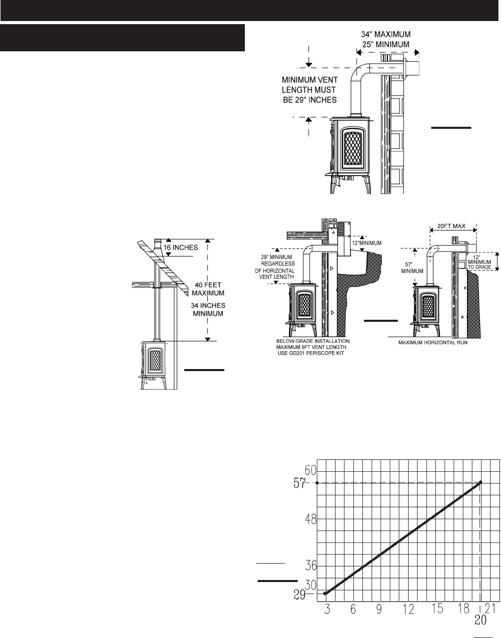
When terminating vertically, the minimum vertical rise is
34 inches above the stove and the maximum vertical rise
is 40 feet. FIGURE 4.
Deviation from the minimum vertical vent length can cre-
ate difficulty in burner start-up and/or carboning.
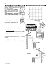
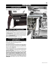
Use an adjustable pipe as the final length of rigid piping
to the stove for ease of installation.
For optimum flame appearance and stove performance,
keep the vent length and number of elbows to a minimum.
The air terminal must remain unobstructed at all times.
Examine the air terminal at least once a year to verify that it
is unobstructed and undamaged.
The maximum horizontal run is 34 inches with a 90
o
elbow
located 29" above the stove. FIGURE 5.
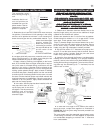
The maximum horizontal run with a 57 inch vertical rise
immediately above the stove is 20 feet . FIGURES 6a & b.
IF VERTICAL RISES GREATER THAN 57 INCHES ARE NECES-
SARY, THE INCREASED RISE MUST BE DEDUCTED FROM THE
MAXIMUM HORIZONTAL RUN.
FIGS 6a-b
FIGURE 5
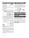
HORIZONTAL RUN NOT TO
EXCEED VERTICAL RISE
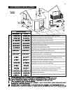
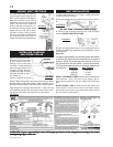
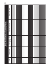
Use the chart on this page to calculate horizontal runs for
vertical rises between 29 and 57 inches. When calculating
maximum run lengths, include 5 feet for each 90° or 45°
elbow.
(DO NOT INCLUDE THE FIRST ELBOW DIRECTLY OFF
THE UNIT.)
FIGURE 4
REQUIRED
VERTICAL
RISE FROM
FIREPLACE
TO FIRST EL-
BOW IN
INCHES
FIGURE 7
CALCULATED HORIZONTAL VENT RUN IN FEET
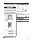
DIRECT VENT SPECIFICS - MODEL GDS60
VENTING LENGTHS &
AIR TERMINAL LOCATIONS