Chapter 1 Introduction
NI-488.2 User Manual 1-2 ni.com
Controlling More Than One Interface
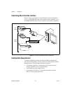
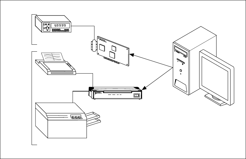
Figure 1-2 shows an example of a multi-interface system configuration.
gpib0 is a PCI-GPIB and is the access interface for the voltmeter. gpib1
is a GPIB-ENET/100 and is the access interface for the plotter and printer.
Figure 1-2. Example of Multiboard System Configuration
Configuration Requirements
To achieve the high data transfer rate that the GPIB was designed for,
you must limit the number of devices on the bus and the physical distance
between devices. The following restrictions are typical:
• A maximum separation of 4 m between any two devices and an
average separation of 2 m over the entire bus.
• A maximum total cable length of 20 m.
• A maximum of 15 devices or controllers connected to each bus,
with at least two-thirds powered on.
One
GPIB
Another
GPIB
Digital
Voltometer
Plotter
Printer
GPIB-ENET/100
PWR/RDY
LINK
10/100
TX RX TALKLISTEN
ENET
GPIB
I
0
gpib0
gpib1


