Appendix A GPIB Basics
NI-488.2 User Manual A-2 ni.com
GPIB Addressing
All GPIB devices and interfaces must be assigned a unique GPIB address.
A GPIB address is made up of two parts: a primary address and an optional
secondary address.
The primary address is a number in the range 0 to 30. The Controller uses
this address to form a talk or listen address that is sent over the GPIB when
communicating with a device.
Most devices just use primary addressing. The GPIB Controller manages
the communication across the GPIB by using the addresses to designate
which devices should be listening or talking at any given moment.
Typically your computer is the GPIB Controller and it manages
communication with your GPIB device by sending messages to it and
receiving messages from it.
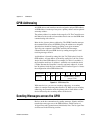
A talk address is formed by setting bit 6, the TA (Talk Active) bit of the
GPIB address. A listen address is formed by setting bit 5, the LA (Listen
Active) bit of the GPIB address. For example, if a device is at address 1,
the Controller sends hex 41 (address 1 with bit 6 set) to make the device
a Talker. Because the Controller is usually at primary address 0, it sends
hex 20 (address 0 with bit 5 set) to make itself a Listener. Figure A-1 shows
the configuration of the GPIB address bits.
Figure A-1. GPIB Address Bits
With some devices, you can use secondary addressing. A secondary
address is a number in the range hex 60 to hex 7E. When you use secondary
addressing, the Controller sends the primary talk or listen address of the
device followed by the secondary address of the device.
Sending Messages across the GPIB
Devices on the bus communicate by sending messages. Signals and lines
transfer these messages across the GPIB interface, which consists of
16 signal lines and 8 ground return (shield drain) lines. The 16 signal lines
are discussed in the following sections.
Bit Position 7 6 5 4 3 2 1 0
Meaning 0 TA LA GPIB Primary Address
(range 0–30)


