


INSTALLATION
L20-378 rev. 0 (9/12) 17
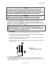
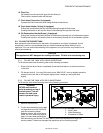
OFF
ON
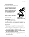
A) Burner Pressure Tap
B) Pilot Adjustment Screw Cap
C) ON/OFF Knob
D) Burner Pressure Adjustment Screw Cap
E) Inlet Pressure Tap
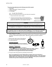
1.8.3. PILOT FLAME ADJUSTMENT
Perform this procedure with the pilot lit.
Note: This procedure requires the use of a DC microammeter.
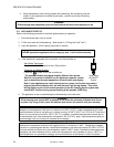
1. Connect the DC microammeter between the flame
sensor terminal and the flame sensor lead. Observe
proper polarity: if the meter needle goes below 0,
reverse the leads. The current reading must be 1.0 A
or greater, (0.15 A or greater for CE units).
2. Adjust the current reading to the required level by
adjusting the pilot flame. Remove the pilot adjustment
screw cap screw to expose the pilot adjustment screw.
Turning the pilot adjustment screw clockwise will
decrease the size of the pilot flame and flame sense
current. Turning the pilot adjustment screw
counterclockwise will increase the pilot flame size and
the flame sense current.
3. Rotate the screw in the direction needed to achieve a
reading of 1.0 A or greater, (0.15 A or greater for CE
units).
Note: Allow 3 to 5 minutes between flame adjustments
to allow the reading to stabilize.
4. Once the pilot flame has been adjusted properly,
replace the pilot adjustment screw cap screw and
remove the microammeter.
1.8.4. MAIN BURNER SYSTEM ADJUSTMENT
For the main burners to operate the gas supply valve must be open and the thermostat must be
turned on. The main power switch must be on. The main burners receive gas from the main gas
supply through the thermostatically controlled valve. When the water temperature drops below
the preset temperature the gas control valve opens.
The main burners must be adjusted to deliver optimum flame. Refer to the following procedure to
adjust the main burners.
1. Ensure that the main gas valve is shut off, remove the manifold pressure tap plug and
connect an accurate pressure gauge (range of 0-16 “W.C. (39.85mbar, 3.98kPa) in 0.1”
(.25mbar, .02kPa) increments) or manometer.
2. Turn on this and all appliances connected to the gas supply line and light their main burners.
The pressure reading of the installed pressure gauge should not drop from the required
installation pressure. Any loss of pressure indicates inadequate supply line installation,
which will cause poor performance of all appliances during peak usage.
3. The installed pressure gauge should be the same, ±0.1” W.C. (.25mbar, .02kPa), as that
marked on the data plate on the inside door of the appliance. If the pressure is correct, go to
step 6, if it is not, adjust the pressure as outlined in step 4.
4. To adjust the pressure, remove the regulator adjustment screw cap and, with a flat head
screwdriver, adjust the regulator screw until the proper burner pressure is reached. Turning
the screw clockwise will increase the burner pressure. Turning the screw counterclockwise
will decrease the burner pressure.