


Spin Fryer I12 Cooking Computer
Pitco P/N 60149505
Page 3 of 28 L22-355 Rev 1
4.8.2 Heat Demand Profile .................................................................................................................................................... 17
4.8.3 Shake Alarm Duration .................................................................................................................................................. 17
4.8.4 Hold Alarm Duration ..................................................................................................................................................... 17
4.8.5 Cancel Duration ............................................................................................................................................................ 17
4.8.6 Configuration Value ...................................................................................................................................................... 17
4.8.7 Factory Reset ............................................................................................................................................................... 18
4.8.8 Standing Pilot Toggle ................................................................................................................................................... 18
4.8.9 Set Network Address .................................................................................................................................................... 18
4.9 To Exit Programming Level 3 ____________________________________________________ 18
5 Factory Menu Level 4 (for the Technician) .................................................................................... 19
5.1 Pitco Collect (toggle) __________________________________________________________ 19
5.2 Offset Temperature Display _____________________________________________________ 19
5.3 Melt Cycle ON Time ___________________________________________________________ 19
5.4 Minimum ON and OFF Cycle Time ________________________________________________ 19
5.5 Recovery Test Values _________________________________________________________ 20
5.6 Diagnostic Menu Entry _________________________________________________________ 20
5.7 Ready Level _________________________________________________________________ 20
5.8 Operating Temperature Range ___________________________________________________ 20
5.9 High Limit Value ______________________________________________________________ 20
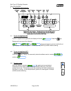
5.10 Spin Diagnostics ____________________________________________________________ 21
5.10.1 Motor On/Off ............................................................................................................................................................ 21
5.10.2 Motor Speed - Increase ........................................................................................................................................... 21
5.10.3 Motor Speed Decrease ............................................................................................................................................ 21
5.10.4 Spin Direction........................................................................................................................................................... 21
5.10.5 Door Open ............................................................................................................................................................... 21
5.10.6 Cook Position Indicator ............................................................................................................................................ 21
5.10.7 Load Position Indicator ............................................................................................................................................ 21
5.10.8 Spin Position Indicator ............................................................................................................................................. 21
5.10.9 Basket Lift Position (Cook) ...................................................................................................................................... 21
5.10.10 Basket Lift Position (Load) ....................................................................................................................................... 21
5.10.11 Basket Lift Position (Spin) ........................................................................................................................................ 21
5.11 Test On/Off ________________________________________________________________ 22
5.12 More Factory Menu Entry _____________________________________________________ 22
5.12.1 Control ID Display .................................................................................................................................................... 22
5.12.2 Set Network Address ............................................................................................................................................... 22
5.13 To Exit Factory Menu (Level 4): ________________________________________________ 22
6 Other Displays: ................................................................................................................................. 23
7 Mechanical Dimensions: ................................................................................................................. 25
8 Electrical Connections at LEFT and RIGHT connectors): ............................................................ 26
9 Probe Resistance Chart: .................................................................................................................. 27