1
(1)
(2)
(3)
(1)
(2)
(3)
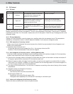
Control time
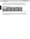
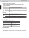
4-2-3. Refrigerant Oil Recovery Control between Systems
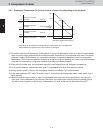
Simplified flow of system refrigerant oil recovery control
Refrigerant oil recovery control between systems shall be performed as the flow mentioned below.
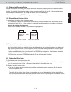
Cooling cycle
4-3-1. Defrost Methods
Maximum 3 minutes (Stops once before and once after control.)
All outdoor units operate at maximum horsepower.
Outdoor units
Electronic Thermostat
Expansion Valve
RAP valve kit
Fan
Indoor
units
Valves at all indoor units operate at a fixed pulse according to the indoor unit capacity.
Valve kits at all indoor units operate in Cooling mode (OFF status.)
Fan operates at the set fan speed, or stops depending on the operation mode of the
indoor unit.
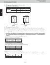
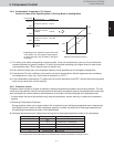
Heating cycle
Control time
Outdoor units
Maximum 3 minutes (Stops once before and once after control.)
All outdoor units operate at maximum horsepower.
Valves at all indoor units operate at 480 pulse.
Valve kits at all indoor units operate in Heating mode (ON status.)
Fan operates at the set fan speed, stops or operates at a very low speed.
Expansion Valve
Electronic Thermostat
RAP valve kit
Fan
Indoor
units
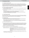
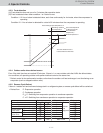
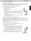
4-3. Defrost Control
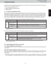
This system uses the following 2 defrosting systems.
System employs Defrost control method
Reverse cycle defrost
Outdoor unit cycle defrost
1 outdoor unit in the refrigerant system
2 outdoor units in the refrigerant system
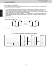
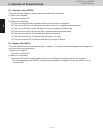
4-3-2. Constraint conditions
Frost detection does not occur for 5 minutes after operation starts.
Defrost does not begin again for 35 minutes of A/C operation after defrost was once completed.
If all indoor units are stopped while defrost control is in effect, or if the outdoor unit is stopped due to protection
control or another reason, then defrost control will not start for a minimum of 10 minutes after restart occurs.
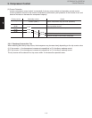
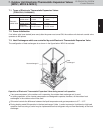
Normal operation 3-minute stop Refrigerant oil recovery control between systems (Max. 3 minutes) 3-
minute stop Normal operation
1 - 10
4. Special Controls
W-2WAY ECO-i SYSTEM
Control Functions


