


2
2 - 5
W-2WAY ECO-i SYSTEM
Outdoor Unit Repair Procedures
3. Discharging Compressor Oil
Discharged oil can be used for checking the condition of the system. Based on the appearance and color of the
discharged oil, a judgment can be made on whether the system is operating normally or not.
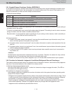
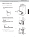
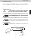
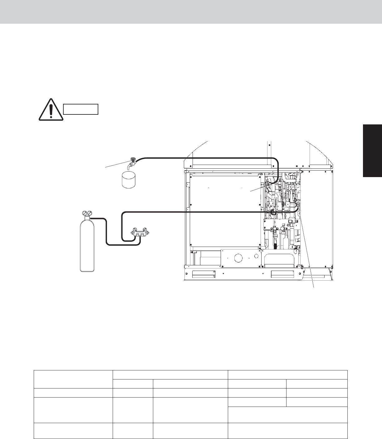
3-1. Discharging Oil from Oil Separator
Recover the refrigerant from the outdoor unit following the procedure given in “5. Recovering Refrigerant.” Install
hoses as indicated on the equipment and feed nitrogen gas gradually to provide pressure to the system from the
low-pressure outlet and collect oil in a pan or container. (Fig. 8)
The low-pressure outlet port is at the Lo side of the right side.
A faulty outdoor unit may remain pressurized. The oil outlet port employs a
Schrader-type push-to-release valve. Be careful to avoid accidental oil release
when using the port.
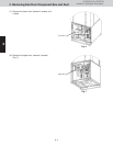
3-2. Discharging Oil in Compressor
Recover the refrigerant in the outdoor unit following the procedures in “5. Recovering Refrigerant.” Remove the
compressor and discharge the oil in it. Refer to “10. Compressor” for detailed procedures.
3-3. Checking the Oil
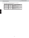
Acceptance/rejection criteria for the oil
It is difficult to measure the total acid value in the field, therefore oil hue and odor are the rule of thumb. Checking
for carbon deposits and abrasive metal powder can additionally be used to assess the system condition.
CAUTION
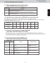
Judgment criteria for changing oil*
Condition of
refrigeration cycle
Color Odor Total acid value Hue
Normal Yellowish None 0.02 or less 3.5 or less
0.06 or over 4.0 or over
Abnormal overheat-
operation
Brownish
Smells somewhat
(not as strong as below)
Changing the oil and system cleaning
with dry-cores are necessary.
Motor burnout
Brownish /
blackish
Pungent / burnt odor
Changing the oil and system cleaning
with dry-cores are necessary.
Condition of oil
Nitrogen gas
Manifold gauge
Packless valve or the like
Container
Low-pressure outlet port
(For 5/16" (7.94mm)-dia. connector)
Oil outlet port
(For 1/4" (6.35mm)
-dia. connector)
Lo Hi
Fig. 8
•
•
*