


2
2 - 12
5. Recovering Refrigerant
W-2WAY ECO-i SYSTEM
Outdoor Unit Repair Procedures
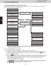
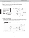
5-2-3. Refrigerant recovery procedures (2): Indoor unit with no ball valve equipped
Refrigerant in all indoor units and the refrigerant tubing circuit must be pumped into the outdoor unit. The maximum
refrigerant storage capacity per a single outdoor unit is approx. 529 oz. Thus, in order to collect all refrigerant from
the system, a separate refrigerant recovery unit is necessary. Follow these procedures to correctly perform pump
down.
Perform work correctly, according to the work procedures given below.
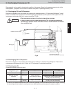
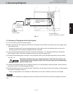
Connect the manifold gauge to the high- and low-pressure outlet ports on the outdoor unit where pump down
will be performed. Be sure that no air enters the tubing at this time.
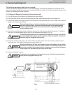
Follow the instructions in “5-2-1. Cooling operation (for all units)” and operate all units in Cooling mode for
approximately 5 minutes. Then fully close the liquid tube valve on the outdoor unit where pump down will be
performed.
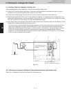
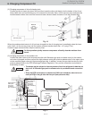
When the high-pressure gauge reaches 406.1 psi or higher, or the low-pressure gauge reaches 72.5 psi or
below, at the outdoor unit where pump down is being performed, press the ON/OFF button on the outdoor unit
maintenance remote controller to stop operation at all units. Then immediately fully close the suction tube valve
on the outdoor unit where pump down is being performed.
* If the outdoor unit maintenance remote controller is unavailable, follow the procedure below to stop all of the
units.
Pull out the SCT connector (2P) (YEL) (CN231) on the outdoor unit control PCB of the unit where pump down
is being performed. When the SCT connector is pulled out, immediately alarm F12 (sensor trouble) occurs
and all outdoor units stop operating. Be sure that you do NOT grasp the lead wire when pulling out the con-
nector. Removing any other connector may not cause the units to stop. Therefore be sure to pull out the SCT
connector only.
It is not necessary to recover the refrigerant from the balance tube. Therefore do
not operate the balance tube valve.
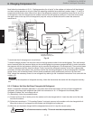
Turn off power to all equipment in the system. Then pull out the RC1 connector (4P) (BLU) (CN106) on the out-
door control PCB in the outdoor unit for which pump down has been completed.
* By pulling out the RC1 connector, communication between the main and the sub outdoor units will be isolated.
Change the setting of controllable outdoor unit numbers (reduce by 1 unit).
* If the setting is incorrect, the E30 alarm (outdoor unit serial communication signal error) occurs and the unit
will not operate.
Turn on power for all equipment in the system and let the remaining outdoor units run in Cooling mode.
Repeat steps and and complete pump down for all outdoor units.
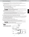
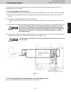
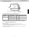
Using hoses with Schrader-type push-to-release valves, connect the manifold gauge valves to the suction line
service port, the discharge line service port and the liquid line service port in the next outdoor unit to undergo
pump down. (Fig. 11)
Remaining refrigerant in the system may cause internal pressure. Check that each
valve on the manifold gauge is tightly closed. A Schrader-type push-to-release
valve is provided for each connection port.
Use hoses to connect the manifold gauge valves, refrigerant recovery unit, and refrigerant recovery cylinder.
Quickly connect each part to prevent air from entering the tubing.
Recover remaining refrigerant from the inter-unit tubing and indoor units using the refrigerant recovery unit.
To determine the completion of refrigerant recovery, follow the instructions that came with the refrigerant recovery
unit.
2
1
NOTE
CAUTION
CAUTION
1
2
3
5
6
7
8
10
9
4