


12
R-820BK
R-820BW
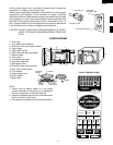
DESCRIPTION AND FUNCTION OF COMPONENTS
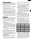
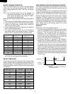
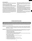
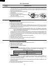
DOOR OPEN MECHANISM
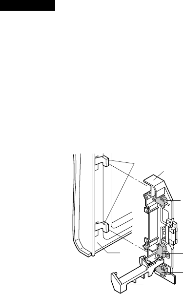
The door is opened by pushing the open button on the
control panel, refer to Figure D-1.
When the open button is pushed, the open button pushes up
the switch lever, and then the switch lever pushes up the
latch head. The latch heads are moved upward and re-
leased from latch hook. Now the door will open.
of the monitor switch contacts.
CAUTION: BEFORE REPLACING A BLOWN MONITOR
FUSE TEST THE DOOR SENSING SWITCH,
PRIMARY INTERLOCK RELAY (RY2), RELAY
(RY6), SECONDARY INTERLOCK SWITCH
AND MONITOR SWITCH FOR PROPER OP-
ERATION. (REFER TO CHAPTER "TEST PRO-
CEDURE").
NOTE: MONITOR FUSE AND MONITOR SWITCH ARE
REPLACED AS AN ASSEMBLY.
TURNTABLE MOTOR
The turntable motor rotates the turntable located on the
bottom of the oven cavity, so that the food on the turntable
cook evenly during cooking. The turntable may turn in either
direction.
COOLING FAN MOTOR
The cooling fan motor drives a blade which draws external
cool air. This cool air is directed through the air vanes
surrounding the magnetron and cools the magnetron. This
air is channelled through the oven cavity to remove steam
and vapors given off from the heating food. It is then
exhausted through the exhausting air vents at the oven
cavity.
MONITOR FUSE
1. The monitor fuse blows when the contacts (COM-NO) of
the primary interlock relay (RY2) and secondary interlock
switch remain closed with the oven door open and when
the monitor switch closes.
2. If the wire harness or electrical components are short-
circuited, this monitor fuse blows to prevent an electric
shock or fire hazard.
THERMAL CUT-OUT 125˚C (MAGNETRON)
This thermal cut-out protects the magnetron against over-
heating. If the temperature goes up higher than 257˚F
(125˚C) because the fan motor is interrupted or the ventila-
tion openings are blocked, the thermal cut-out will open and
line voltages to the high voltage transformer will be cut off
and the operation of the magnetron will be stopped. The
thermal cut-out will not resume.
THERMAL CUT-OUT 170˚C (OVEN)
The thermal cut-out located on the top of the oven cavity is
designed to prevent damage to the oven if the food in the
oven catch fire due to over heating produced by improper
setting of the cooking time or failure of control unit. Under the
normal operation, the oven thermal cut-out remains closed.
However, when abnormally high temperatures are reached
within the oven cavity, the oven thermal cut-out will open at
338˚F(170˚C) causing the oven to shut down. The thermal
cut-out will close in at 311˚F(155˚C).
TOP HEATERS
The top heaters are located on the top of the oven cavity
assembly. The top heaters send out heat to grill foods.
Figure D-1. Door Open Mechanism
DOOR SENSING AND SECONDARY INTERLOCK
SWITCHES
The secondary interlock switch is mounted in the lower
position of the latch hook and the door sensing switch in the
primary interlock system is mounted in the upper position of
the latch hook. They are activated by the latch heads on the
door. When the door is opened, the switches interrupt the
power to all high voltage components. A cook cycle cannot
take place until the door is firmly closed thereby activating
both interlock switches. The primary interlock system con-
sists of the door sensing switch and primary interlock relay
located on the control circuit board.
MONITOR SWITCH
The monitor switch is activated (the contacts opened) by the
latch head on the door while the door is closed. The switch
is intended to render the oven inoperative, by means of
blowing the monitor fuse, when the contacts of the primary
interlock relay (RY2) and secondary interlock switch fail to
open when the door is opened.
Functions:
1. When the door is opened, the monitor switch contacts
close (to the ON condition) due to their being normally
closed. At this time the primary interlock relay (RY2) and
secondary interlock switch are in the OFF condition
(contacts open) due to their being normally open contact
switches.
2. As the door goes to a closed position, the monitor switch
contacts are first opened and then the door sensing
switch and the secondary interlock switch contacts close.
(On opening the door, each of these switches operate
inversely.)
3. If the door is opened, and the primary interlock relay
(RY2) and secondary interlock switch contacts fail to
open, the monitor fuse blows simultaneously with closing
Latch Hook
Door
Sensing
Switch
Monitor
Switch
Secondary
Interlock
Switch
Switch
Lever
Latch
Heads
Door