


34
R-820BK
R-820BW
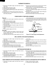
DOOR SENSING SWITCH/SECONDARY INTERLOCK SWITCH AND MONITOR SWITCH REMOVAL
1. Disconnect the power supply cord and then remove
outer case.
2. Open the door and block it open.
3. Discharge high voltage capacitor.
4. Now, the back plate with the sub back plate should be
removed.
5. Disconnect the connector CN-D from the control unit.
6. Remove the one (1) screw holding the air duct to the
oven cavity rear plate.
7. Remove the air duct with the air guide cover and the
partition plate from the oven cavity rear plate.
8. Remove the one (1) screw holding the thermistor angle
to the oven cavity rear plate.
9. Remove the thermistor angle together with thermistor
from the oven.
10.Straighten the tab of the thermistor angle holding the
thermistor to the thermistor angle.
11.Remove the thermistor from the thermistor angle
Removal
1.
Disconnect the power supply cord and
then
remove outer
case.
2. Open the door and block it open.
3. Discharge high voltage capacitor.
4. Remove the one (1) screw holding the green wire to the
cavity rear plate.
5. Disconnect the leads of the power supply cord from the
main wire harness.
6. Release the power supply cord from the oven cavity rear
plate.
7. Now, the power supply cord is free.
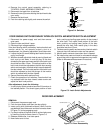
Re-install
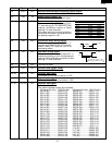
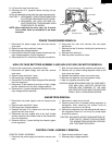
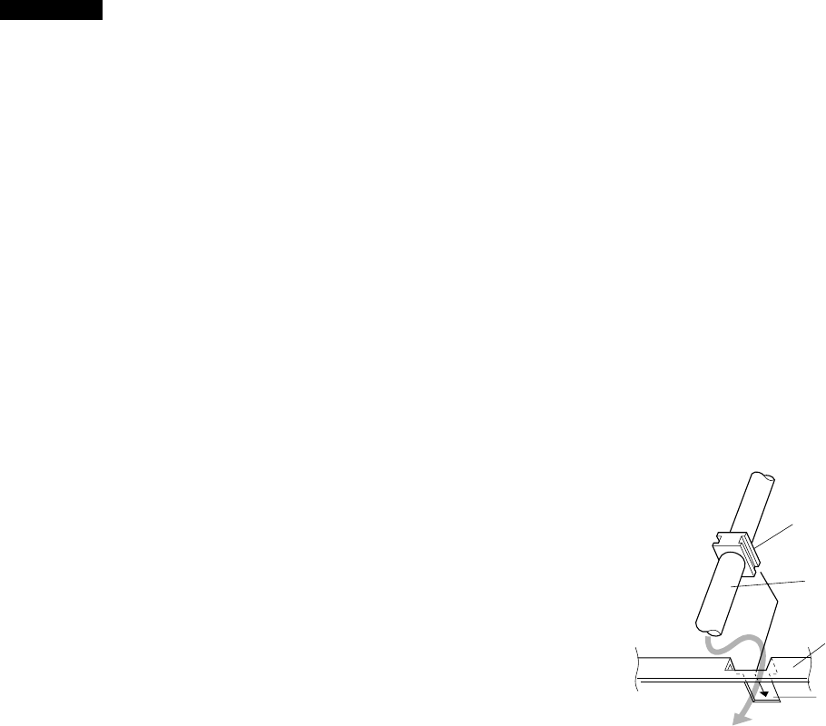
1. Insert the moulding cord stopper of power supply cord
into the square hole of the oven cavity rear plate,
referring to the Figure C-3.
2. Install the earth wire lead of power supply cord to the
POWER SUPPLY CORD REPLACEMENT
Figure C-3. Power Supply Cord Replacement
Power
Supply Cord
Moulding
Cord Stopper
Oven Cavity
Rear Plate
Square Hole
cavity rear plate with one (1) screw and tighten the screw.
3. Connect the brown and blue wire leads of power supply
cord to the main wire harness correctly, referring to the
Pictorial Diagram.
1. Disconnect the power supply cord and then remove
outer case.
2. Open the door and block it open.
3. Discharge high voltage capacitor.
4. Remove the one (1) screw holding the exhaust duct to
the oven cavity.
5. Remove the exhaust duct from the oven cavity.
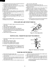
6. Disconnect the wire leads from the grill heaters.
7. Lay down the two (2) tabs holding the reflector to the
GRIL HEATER (TOP HEATER) REMOVAL
oven cavity.
8. Remove the reflector from the oven cavity by sliding it
leftward.
9. Remove the grill heaters and the short terminal together
from the oven cavity top plate.
10.Remove the two (2) screws holding the short terminal to
the grill heaters.
11.Now the individual grill heaters are free.
1. Disconnect the power supply cord and then remove
outer case.
2. Open the door and block it open.
3. Discharge high voltage capacitor.
4. Remove the fan duct from the oven cavity, referring to
"FAN MOTOR REPLACEMENT".
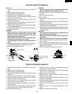
5. Disconnect the wire leads from the bottom heater.
BOTTOM HEATER REMOVAL
6. Remove the two (2) nuts holding the bottom heater with
the bottom heater angle and the heat seal spring to the
oven cavity right wall.
7. Remove the two (2) nuts holding the bottom heater with
the bottom heater angle and the heat seal spring to the
oven cavity left wall.
8. Remove the bottom heater from the oven cavity .
1. Disconnect the power supply cord and then remove
outer case.
2. Open the door and block it open.
3. Discharge high voltage capacitor.
THERMISTOR REMOVAL