


18
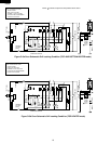
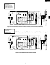
R-820BK
R-820BW
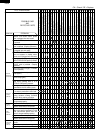
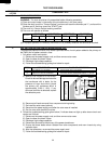
H BLOWN MONITOR FUSE TEST
TEST PROCEDURES
PROCEDURE
LETTER
COMPONENT TEST
1. Disconnect the power supply cord, and then remove outer case.
2. Open the door and block it open.
3. Discharge high voltage capacitor.
4. If the monitor fuse is blown when the door is opened, check the primary interlock relay, secondary
interlock switch and monitor switch according to the "TEST PROCEDURE" for those switches before
replacing the blown monitor fuse.
CAUTION: BEFORE REPLACING A BLOWN MONITOR FUSE, TEST THE PRIMARY INTERLOCK
RELAY, SECONDARY INTERLOCK SWITCH, DOOR SENSING SWITCH AND MONITOR
SWITCH FOR PROPER OPERATION.
If the monitor fuse is blown by improper switch operation, the monitor fuse and monitor switch must
be replaced with "monitor fuse and monitor switch assembly" part number FFS-BA021WRK0, even
if the monitor switch operates normally. The monitor fuse and monitor switch assembly is comprised
of a 20 ampere fuse and switch.
5. Reconnect all leads removed from components during testing.
6. Reinstall the outer case (cabinet).
7. Reconnect the power supply cord after the outer case is installed.
8. Run the oven and check all functions.
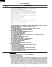
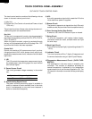
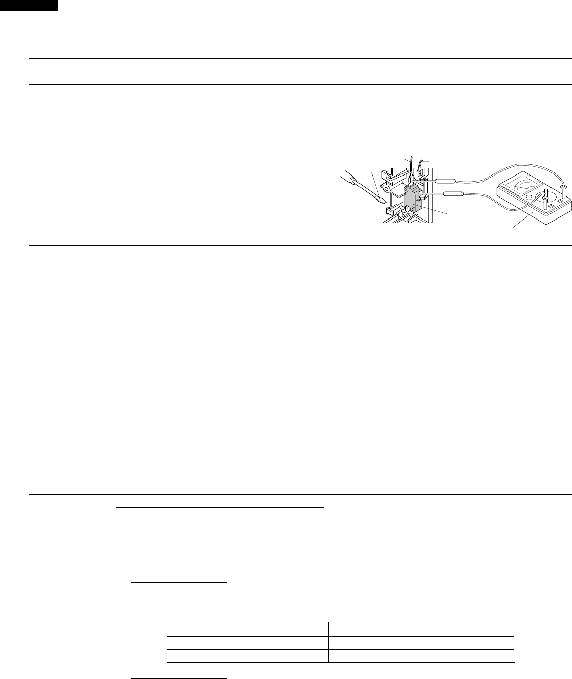
with the door opened (in this condition the plunger of the monitor switch is pushed in), the meter should
indicate an open circuit. If improper operation is indicated, the switch may be defective. After testing
the monitor switch, reconnect the wire lead to the monitor switch (COM) terminal and check the
continuity of the monitor circuit.
5. Reconnect all leads removed from components
during testing.
6. Reinstall the outer case (cabinet).
7. Reconnect the power supply cord after the
outer case is installed.
8. Run the oven and check all functions.
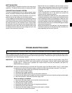
SCREW
DRIVER
RED
WHT
MONITOR
SWITCH
OHMMETER
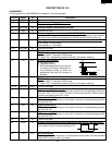
I TOP HEATERS AND BOTTOM HEATER TEST
1. Disconnect the power supply cord, and then remove outer case.
2. Open the door and block it open.
3. Discharge high voltage capacitor.
4. Make sure the heater is cooled completely.
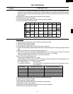
5. Resistance of heater.
Disconnect the wire leads to the heater to be tested. Using ohmmeter with low resistance range.
Check the resistance across the terminals of the heater as described in the following table.
Table: Resistance of heater
Parts name Resistance
Top heaters Approximately 7.2 Ω x 2 = 14.4 Ω
Bottom heater Approximately 28.8 Ω
6. Insulation resistance.
Disconnect the wire leads to the heater to be tested. Check the insulation resistance between the
heater terminal and cavity using a 500V - 100MΩ insulation tester. The insulation resistance should
be more than 10 MΩ in the cold start.
7. If the results of above test 5 and/or 6 are out of above specifications, the heater is probably faulty and
should be replaced.
8. Reconnect all leads removed from components during testing.
9. Reinstall the outer case (cabinet).