


31
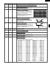
R-820BK
R-820BW
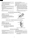
POWER TRANSFORMER REMOVAL
6. Disconnect the main wire harness from the power
transformer.
7. Remove the two (2) screws holding the transformer to
base plate.
8. Remove the transformer.
9. Now the power transformer is free.
1. Disconnect the power supply cord and then remove
outer case.
2. Open the oven door and block it open.
3. Discharge high voltage capacitor.
4. Disconnect the filament leads of power transformer from
high voltage capacitor and the magnetron.
5. Disconnect the H.V. wire B from the power transformer.
8. Lift the entire case from the oven.
9. Discharge the H.V. capacitor before carrying out any
further work.
10.Do not operate the oven with the outer case removed.
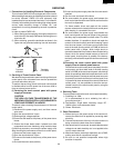
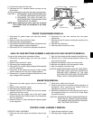
CAUTION: 1. DISCONNECT OVEN FROM POWER SUP
PLY BEFORE REMOVING OUTER CASE.
2. DISCHARGE THE HIGH VOLTAGE CA-
PACITOR BEFORE TOUCHING ANY OVEN
COMPONENTS OR WIRING.
NOTE: When replacing the outer case, the 2 special
Torx screws must be reinstalled in the same
locations.
HIGH VOLTAGE RECTIFIER ASSEMBLY AND HIGH VOLTAGE CAPACITOR REMOVAL
To remove the components, proceed as follows.
1. Disconnect the power supply cord and then remove
outer case.
2. Open the door and block it open.
3. Discharge high voltage capacitor.
4. Disconnect H.V. wire of the high voltage rectifier assembly
from the magnetron.
5. Disconnect all the leads and terminals of high voltage
rectifier assembly from the high voltage capacitor.
6. Remove one (1) screw holding earth side terminal of the
high voltage rectifier assembly.
7.
Now, the high voltage rectifier assembly should be free.
8. Remove one (1) screw holding capacitor holder to the
oven cavity rear plate.
9. Release the capacitor holder from the fan duct.
10.Remove the capacitor from the capacitor holder.
11.Now, the capacitor should be free.
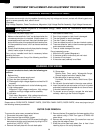
CAUTION: WHEN REPLACING HIGH VOLTAGE RECTI-
FIER AND HIGH VOLTAGE CAPACITOR,
GROUND SIDE TERMINAL OF THE HIGH
VOLTAGE RECTIFIER MUST BE SECURED
FIRMLY WITH A GROUNDING SCREW.
1. Disconnect the power supply cord and remove outer
case.
2. Open the door and block it open.
3. Discharge high voltage capacitor.
4. Release the tabs of air intake duct from the chassis
support and the oven cavity.
5. Disconnect the high voltage wire of the high voltage
rectifier assembly and filament lead of the transformer
from the magnetron.
6. Remove the one (1) screw holding the chassis support
to the magnetron.
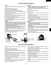
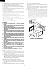
MAGNETRON REMOVAL
7. Move the air intake duct to the left.
8. Carefully remove four (4) screws holding magnetron to
waveguide, when removing the screws hold the
magnetron to prevent it from falling.
9. Remove the magnetron from the waveguide with care so
the magnetron antenna is not hit by any metal object
around the antenna.
CAUTION: WHEN REPLACING THE MAGNETRON, BE
SURE THE R.F. GASKET IS IN PLACE AND
THE MAGNETRON MOUNTING SCREWS
ARE TIGHTENED SECURELY.
CONTROL PANEL ASSEMBLY
1.
Disconnect the power supply cord and
then
remove outer
case.
CONTROL PANEL ASSEMBLY REMOVAL
2. Open the door and block it open.
3. Discharge high voltage capacitor.
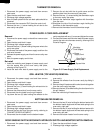
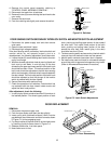
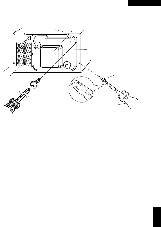
LHSTIX
Screw
Driver(Size LR-4)
LHSTIX Screw
Back Plate
Outer Case Cabinet
Sub Back Plate
Special
screw
Screw Driver
(Type: TORX T20 H or
GTXH20-100)