


26
R-820BK
R-820BW
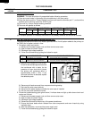
Pin No. Signal I/O Description
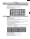
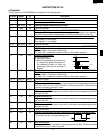
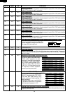
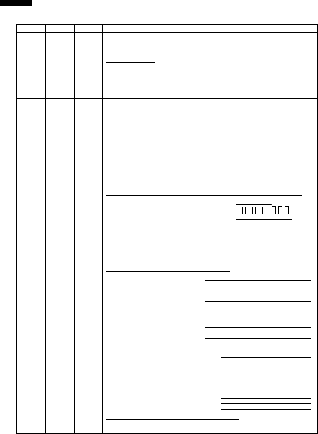
VARI ON TIME OFF TIME
P-HI(100% power) 32 sec. 0 sec.
P-90(approx. 90% power) 30 sec. 2 sec.
P-80(approx. 80% power) 26 sec. 6 sec.
P-70(approx. 70% power) 24 sec. 8 sec.
P-60(approx. 60% power) 22 sec. 10 sec.
P-50(approx. 50% power) 18 sec. 14 sec.
P-40(approx. 40% power) 16 sec. 16 sec.
P-30(approx. 30% power) 12 sec. 20 sec.
P-20(approx. 20% power) 8 sec. 24 sec.
P-10(approx. 10% power) 6 sec. 26 sec.
P-0(0% power) 0 sec. 32 sec.
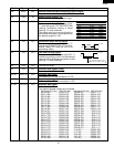
Power output ON time OFF time
100 % 48 sec. 0 sec.
90 % 44 sec. 4 sec.
80 % 40 sec. 8 sec.
70 % 36 sec. 12 sec.
60 % 32 sec. 16 sec.
50 % 26 sec. 22 sec.
40 % 22 sec. 26 sec.
30 % 16 sec. 32 sec.
20 % 12 sec. 36 sec.
10 % 8 sec. 40 sec.
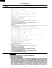
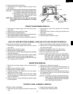
During cooking
L
H
16.7 msec.
26 P40 OUT Key strobe signal.
Signal applied to touch-key section. A pulse signal is input to P44 - P47 terminal while
one of G7 line key on matrix is touched.
27 P77 OUT Key strobe signal.
Signal applied to touch-key section. A pulse signal is input to P44 - P47 terminal while
one of G6 line key on matrix is touched.
28 P76 OUT Key strobe signal.
Signal applied to touch-key section. A pulse signal is input to P44 - P47 terminal while
one of G5 line key on matrix is touched.
29 P75 OUT Key strobe signal.
Signal applied to touch-key section. A pulse signal is input to P44 - P47 terminal while
one of G4 line key on matrix is touched.
30 P74 OUT Key strobe signal.
Signal applied to touch-key section. A pulse signal is input to P44 - P47 terminal while
one of G3 line key on matrix is touched.
31 P73 OUT Key strobe signal.
Signal applied to touch-key section. A pulse signal is input to P44 - P47 terminal while
one of G2 line key on matrix is touched.
32 P72 OUT Key strobe signal.
Signal applied to touch-key section. A pulse signal is input to P44 - P47 terminal while
one of G1 line key on matrix is touched.
33 P71 OUT Oven lamp and turntable motor driving signal(Square Waveform : 60Hz).
To turn on and off shut-off relay (RY6). The
square waveform voltage is delivered to
the relay (RY6) driving circuit.
34 P70 IN Connected to VC.
35 RESET IN Auto clear terminal.
Signal is input to reset the LSI to the initial state when power is applied. Temporarily
set to "L" level the moment power is applied, at this time the LSI is reset. Thereafter
set at "H" level.
36 P81 OUT Magnetron high-voltage circuit driving signal.
To turn on and off the cook relay
(RY2). In P-HI operation, the sig-
nals hold "L" level during microwave
cooking and "H" level while not cook-
ing. In other cooking modes (P-90,
P-80, P-70, P-60, P-50, P-40, P-30,
P-20, P-10, P-0) the signal turns to
"H" level and "L" level in repetition
according to the power level.
37 P80 OUT Grill heaters (TOP HEATER) driving signal.
To turn on and off the grill heaters relay
(RY3). "L" level during grill (TOP GRILL,
TOP AND BOTTOM) cooking, Con-
vection cooking or Roast cooking, "H"
level otherwise.
The heater relay turns on and off within
a 48 second time base in accordance
with the special program in LSI.
38 XIN IN Internal clock oscillation frequency input setting.
The internal clock frequency is set by inserting the ceramic filter oscillation circuit with
respect to XIN terminal.