


SEZ SERIES COUNTERTOP STEAMERS TROUBLESHOOTING
OPERATOR’S MANUAL 1183437 PAGE 25
TROUBLESHOOTING
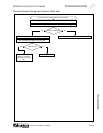
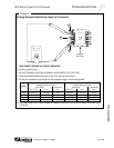
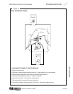
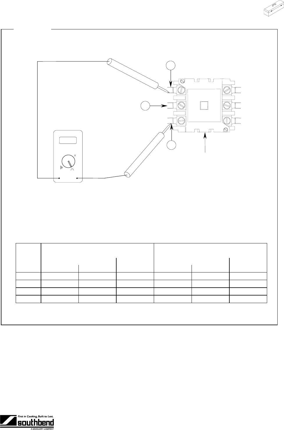
Figure 8
Heating Element Resistance Check (at Contactor)
B
A
Contactor
(top view)
C
1. DISCONNECT POWER AT CIRCUIT BREAKER.
2. Remove control panel.
3. DO NOT REMOVE HEATING ELEMENT LEAD WIRES FOR THIS TEST.
4. Place test leads between terminals A and C on left side of contactor.
5. Check the resistance and compare to the allowable range in the following table:
Model SEZ/3 Model SEZ/5
Allowable Resistance (Ohms) Allowable Resistance (Ohms)
Three-Phase Single-Phase Three-Phase Single-Phase
Voltage
A-B or B-C A-C A-C A-B or B-C A-C A-C
208 10 to 12 14 to 16 5 to 6 8 to 10 11 to 13 4 to 5
220 12 to 13 15 to 18 6 to 7 9 to 11 13 to 15 5 to 6
240 14 to 16 18 to 21 7 to 9 11 to 13 15 to 17 6 to 7
480 55 to 64 73 to 85 29 to 34 45 to 52 60 to 70 24 to 28
6. For three-phase units, check resistance between terminals A and B and between terminals B and
C similarly.