


11
GLASSWELL— DISPENSER MODELS
The dispenser area of Models ICBBI-42SD and
I
CBBI-48SD has been engineered to enablethe
use ofthe overlay/flush inset panel application.
Installingoverlay/flushinset panels for these
models is the same procedure as for other Built-
In models. The refrigerator door panel will need
to accommodate a cut-out forthe glasswell
bezel.
T
o remove the glasswell bezelfor an overlay/
flush inset Model ICBBI-42SD or ICBBI-48SD, the
water grille and touch pad must be removed. Lift
the water grille up and out. Next, remove the
touch pad assembly which is taped in place, by
removing the center plastic mandrel supports.
Carefully tilt the touch pad out and disconnect
the wire harness (blue side up) from the back
side of the touchpad. Removethe bezelby
removing the four screws.
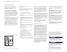
GRILLE PANEL ASSEMBLY
Remove the inner grille panel assembly as
d
escribed in Grille Removal, page 8. Remove the
top twocorner screws andpull away the top
frame. Slide the panel into position in the grille
frame. If you are using a grille panel 6 mm or
thinner, you will need to install a filler.
R
eattach the top frame by reinstalling the two
top corner screws. Install theinner grille panel
a
ssembly onto the unit, by reversing the proce-
dure outlined in Grille Removal, page 8.
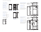
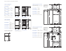
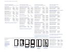
Refer to specificationsfor Overlay GrillePanels
on page12, and the illustration on page 10, for
the exact sizing of all three panels.
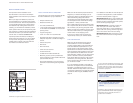
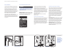
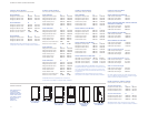
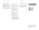
Water
Grille
Ice
Key Pad
Light
Key Pad
Water
Key Pad
Touch Pad
Lock
Indicator
Bezel
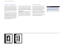
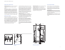
Glasswell—dispensermodels Glasswell bezel removal
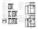
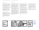
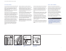
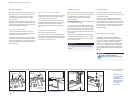
OVERLAY PANEL INSTALLATION
Insert the overlay/flush inset panelinto the door
t
rim. Reverse the procedure to install the bezel,
touch pad and water grille. To install the plastic
rivets, insert rivets through the touch pad and
into the control housing and secure by pressing
mandrels into the body of the rivets. Refer to the
illustrations below.
IMPORTANT NOTE:
The total panelthickness
(
including backer and spacer, if used) in the
glasswell bezelarea can range from 6 mm toa
maximum of 29 mm. If the panel is thicker, provi-
sions must be made to rout out a space to
accommodate the bezel surrounding the glass-
well.
Do notexceed the paneldimensions listed
for the appropriate overlay grille panel you
are specifying. The overlay decorative panel
cannotbeany larger oritmay restrict the air
flow to the compressor areaand cause
problems with theoperation of the Sub-Zero
unit.
CAUTION