


13
FLUSH INSET PANEL INSTALLATION
FLUSH INSET PANELS
If your customer has chosen the flush inset panel
a
pplication, make sure that the panels you are
about to install match dimensions listed in the
Flush Inset Panel Specifications on page 14.
IMPORTANT NOTE:
The size of the flush inset
panel is critical. It must be sized correctly for a
p
roper fit inside theopening.
Overlay/flush inset models are shipped without
h
andle hardware. The cabinet manufacturer or
designer will providehandle hardware atthe job
site to match the overalldecorating scheme.
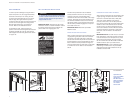
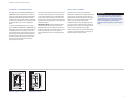
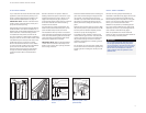
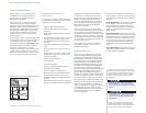
To installflush inset panels, first remove the
door trim molding. For side-by-side models and
the upper door for over-and-under models, insert
a screwdriver tip into the top corner slot on the
handle side and pop outthe trim molding.
Remove the screws and frame. For the drawer
on over-and-under models, insert a screwdriver
tip into the slot on either side of the trim
molding running alongthe top of the drawer,
and popout the trim molding. Removethe
screws and frame. Refer to the illustrations
below.
Sub-Zero allows a 6 mmspace to slide the
b
acking materialinto placeinthe frame.Ifyour
material is thicker than a 6 mm,either rout an
edge around thepanel to get a proper fitor
mount the decorative overlay panelona sheetof
6 mm thick material and insert the backing
material into the channel.
You must allow for 3 mm space between the
b
acker board and the decorative panel, so the
panel will slide easily into the door frame.
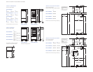
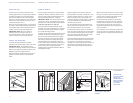
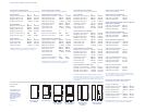
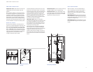
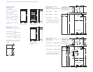
The illustrations below provide a cross section
view ofthe three panelassembly showing place-
ment of the door/drawer/grille trim and a rear
view ofthe three panelassembly with critical
dimensions, standard for all models.
IMPORTANT NOTE:
With the panels installed,
13 mm minimum reveals must be kept on all
sides to ensure proper door opening and suffi-
cient cooling of the unit.
Door/Drawer/
Grille Trim
14
mm
16
mm
6 mmBacker Panel
8 mm min
3
mm
Spacer Panel
Flush Inset Panel
Spacer Panel
Flush Inset Panel
6 mm
Backer
Panel
3 mm
~19
mm
Flush inset panels—cross
section
Flush inset panels—three
panel assembly
Door trim Over-and-under drawer trim
Install the handle hardware beforeinserting the
p
anel. We recommend largerD-style pulls. The
use ofsmall, one-piece knobs is not recom-
mended. If you use screws with thick heads, you
will need to countersink thescrews into the
backer panel before sliding the assembly into
p
lace.
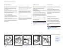
Slide the panel intothe frame on the door. With
t
he panel in position, replace the frame end. Be
sure the panel is inserted completely into the
channel for proper fit and alignment.
To reinstall the trim moldingon side-by-side
models and the upper doorfor over-and-under
models, insert the top of the trim molding into
the grooves at the top of the door and work
downward, snapping the trim molding into the
clips on the frame.
For the drawer on over-and-under models, start
at one end and move towards the opposite end,
snapping the trim molding into the clips on the
frame.
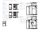
GRILLE PANEL ASSEMBLY
Remove the inner grille panel assembly as
d
escribed in Grille Removal, page 8. Remove the
top twocorner screws andpull away the top
frame. Slide the panel into position in the grille
frame. If you are using a grille panel 6 mm or
thinner, you will need to install a filler.
R
eattach the top frame by reinstalling the two
top corner screws. Install theinner grille panel
a
ssembly onto the unit, by reversing the proce-
dure outlined in Grille Removal, page 8.
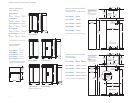
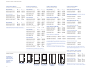
Refer to specificationsfor Flush InsetGrille
Panels on page 14, and the illustration belowfor
the exact sizing of all three panels.
Do notexceed the paneldimensions listed
for the appropriate flush inset grille panel
you are specifying. Theflush inset decorative
panel cannot be any larger or it may restrict
the air flow to the compressor areaand
cause problems with the operation of the
Sub-Zero unit.
CAUTION