


8
BUILT-IN INSTALLATION INSTRUCTIONS
ANTI-TIP BRACKET
INSTALLATION
IMPORTANT NOTE:
Placement of the anti-tip
brackets is critical to a stable installation. Failure
to properly position theanti-tip brackets will
prevent them from engagingthe unit.
Back Grille
Screw
Front Grille Screw
Grilleremoval
Grillemounting screws
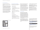
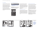
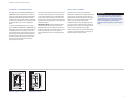
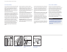
GRILLE REMOVAL
In order to prevent damage to the grille and to
a
ccess the power cord, the top grille assembly
should be removed prior to movingthe unit.
To remove the grille assembly, pull out on the
bottom edge of the grille and tilt it upward.
Loosen the back two grille mounting screws and
r
emove the front two grille mounting screws.
With the grille heldfirmly, pullforward to
r
emove. Refer to the illustrations below.
To reinstall the grille,insert thegrille into
position and be sure that the grillecatch tabs are
engaged. Reinstall the front two grille screws,
then retighten the back two grille screws. Check
for proper fit.
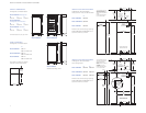
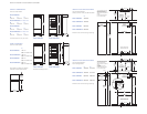
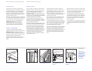
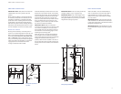
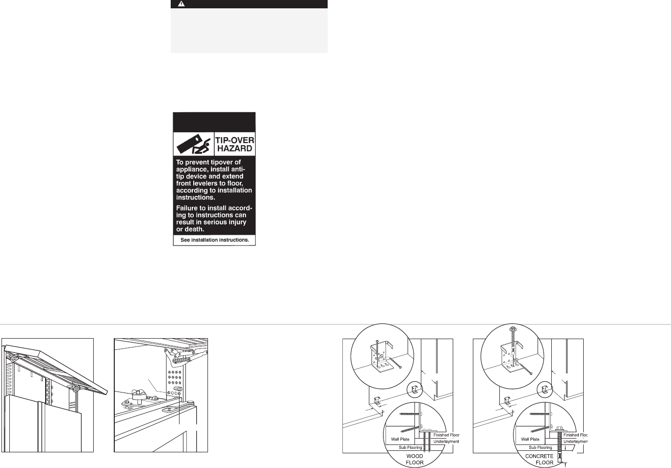
Wood floors
The twoanti-tip brackets must be installed
e
xactly 610 mm from the front of the rough
opening to the back of the brackets and a
minimum of 102 mm from the sides of the rough
opening. This depth will increase to 665 mm for
a flush inset installation based on 19 mm deep
decorativepanels. Proper placement will ensure
that the anti-tip brackets engage the anti-tip bar
at the back of the unit.
IMPORTANT NOTE:
Both anti-tip brackets
MUST be used.
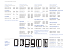
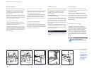
WOOD FLOOR APPLICATIONS
After properly locating the anti-tip brackets in the
rough opening, drill pilotholes 5 mm diameter
maximum in the wall studsand/or wall plate.
Use the #12 x 64 mm PH pan HD zinc screws and
#12 flat washers to secure the brackets in place.
Be sure that the screws penetrate through the
flooring material and into wall studs or wall plate
a minimum of 19 mm. Refer to the illustration
below.
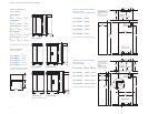
CONCRETE FLOOR APPLICATIONS
A
fter properly locating the anti-tip brackets in the
rough opening, drill pilotholes 5 mm diameter
m
aximum in the wall studs and/or wall plate.
Then drill 10 mm diameterholes intothe
concrete a minimum of 13 mm deep. Use the
#12 x 64 mm PH pan HD zinc screws and #12 flat
washers to secure the bracketstothe wall and
u
se the10mm–16 x 95 mm wedge anchors to
secure the brackets to the floor. Be sure that the
screws penetrate the wall studs or wall plate a
minimum of 19 mm. Refer to the illustration
below.
IMPORTANT NOTE:
For either woodor concrete
floor applications, if the #12 x 64mm screws do
not hita wall stud or the wall plate in any of the
back holes of thebrackets, use the provided
#8–18 x 32mm PH truss HD screws and#12 flat
washers with the nylon zip-it wall anchors.
IMPORTANT NOTE:
In some installations the
subflooring or finished floormay necessitate
angling the screws used to fasten the anti-tip
brackets to the back wall.
102 mm
MIN
610 mm
13 mm
MIN
Concrete floors
102 mm
MIN
610 mm
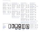
ACCESSORIES
Optional acces-
soriesare available
through your
Sub-Zero dealer. To
obtainlocal dealer
information,visit
our website,
subzero.com.
To preventthe unitfrom tipping forward and
provide a stableinstallation,the unitmust be
secured in placewith the anti-tip brackets
shipped with the unit.
WARNING