


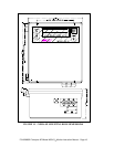
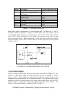
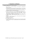

Output Description Normal Operating State
1 Power OK ON
2 Diagnostics Mode(Instrument not
monitoring)
OFF
3 Temperature Fault OFF
4 Pressure Fault OFF
5 UV Lamp Fault OFF
6 Flow Fault OFF
7 Performing Auto-Zero Calibration OFF
8-11 Not Used N/A
12 System OK(no faults) ON
TABLE 1.1 DIGITAL OUTPUTS
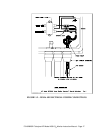
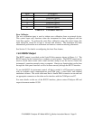
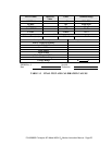
Each digital output is configured as a Collector/Emitter pair. The labels are ‘C’ and ‘E’
for these contacts, respectively. Figure 1.2 below shows the most common way of
connecting the digital outputs to an external device such as PLC. Note: Most devices,
such as PLC’s, have internal provision for limiting the current that the input will draw
from an external device. When connecting to a unit that does not have this feature,
external dropping resistors must be used to limit the current through the transistor output
to 50mA or less.
FIGURE 1.5 - CONNECTING DIGITAL OUTPUTS
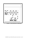
1.6.4 Control Inputs
There are 6 digital control inputs on the rear panel; they are labeled ‘CONTROL IN’ (See
Figure 1.4.) The control inputs are used for remote control of the M450H by a device
such as a PLC. These inputs are triggered by providing a contact closure or low
impedance current path between the + and ground contacts. This can be done by using a
mechanical switch or isolated transistor type output from another device, such as a PLC.
Never connect a voltage level output from another device to these contacts. The
functions of the control inputs is summarized below in Table 1.2:
P/N 02826B1 Teledyne API Model 450H O
3
Monitor Instruction Manual - Page 20