


2.2 Front Panel Display
This section describes the operator interface from the point of view of the front panel.
The front panel consists of a 2-line by 40-character alphanumeric display, 8 pushbuttons,
and 3 status LED’s. Each of these features is described below.
2.2.1 Front panel display fields
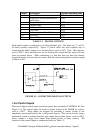
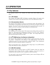
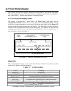
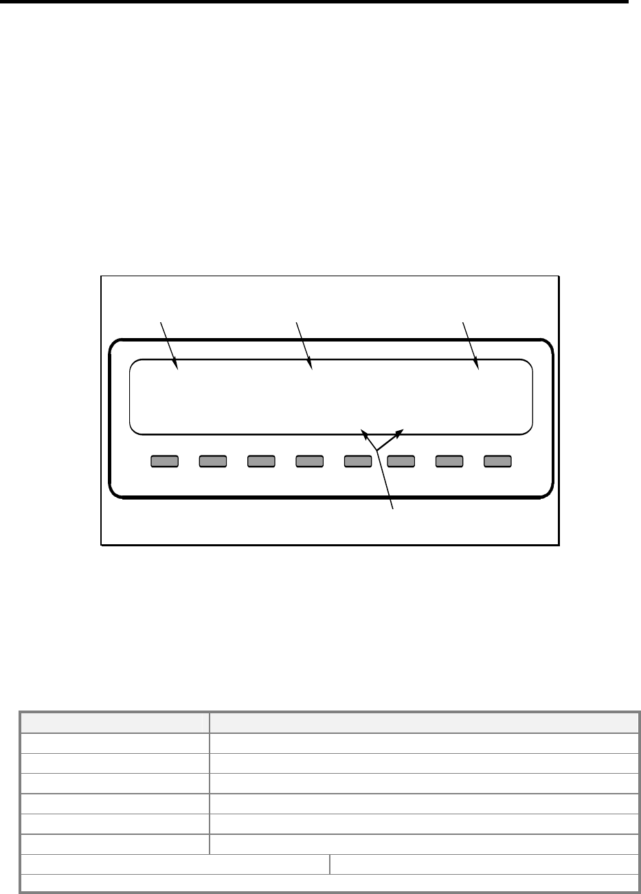
The display is divided into 4 main "fields": the Mode field in the upper left, the
Message/Test Function field in the top center, the ozone Concentration field consisting
of the most recent instantaneous ozone value field in the upper right, and the Menu field
which occupies the entire bottom line of the display. The Menu field is used to define the
function of the 8 pushbuttons directly below the display. The buttons are then used for
selecting menu items and are also used for entering values such as alarm levels. A
typical display is shown in Figure 2.1.
<TST
TST> ALRM MSG CLR SETUP
SAMPLE TIME=15:58:21 12.0 wt%
MODE
FIELD
MESSAGE/TEST
MEASUREMENT FIELD
CONCENTRATION
FIELD
BUTTON DEFINITIONS
FIGURE 2.1 - MODEL 450H FRONT PANEL
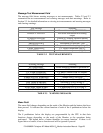
Mode Field
The mode field indicates the current mode of the Monitor. Table 2.1 lists all the possible
modes in the Monitor and their meanings.
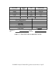
TABLE 2.1 SYSTEM MODES
Mode Meaning
SAMPLE Monitoring
ALARM STATUS Display of Alarm Status
SETUP xxx (1) Configuring monitor (monitoring continues)
DIAG CAL Calibration Menu
DIAG D/A Configure and Calibrate Digital to Analog converters
DIAG AOUT Test analog output
DIAG CFG Instrument Configuation List
(1) xxx = software revision (e.g. A.9)
P/N 02826B1 Teledyne API Model 450H O
3
Monitor Instruction Manual - Page 28