


UV-SVN03D-EN 15
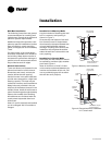
General Installation Checks
The checklist below is a summary of
the steps required to successfully in-
stall a unit. This checklist is intended to
acquaint the installing personnel with
procedures required in the installation
process. It does not replace the de
-
tailed instructions called out in the ap-
plicable sections of this manual.
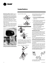
1 Carefully remove the stretch wrap
and top cardboard cover. Check
the unit for shipping damage and
material shortage; file a freight
claim and notify appropriate sales
representation. If end panels have
been ordered, the panel will al
-
ready be mounted to the unit.
Note: The unit ventilator is pack-
aged in clear stretch wrap to allow
for immediate visual inspection. A
protective cardboard cover helps
prevent scratching and other cos
-
metic blemishes during transport.
2 Remove remaining cardboard
blocking.
3 Remove the unit’s left front panel
to verify nameplate/sales order
number is correct. It is located be
-
hind the control box.
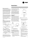
4 Remove shipping bracket from the
lower rear corners of the unit to
separate the unit from the skid. Ac
-
cess to the screws holding the
bracket to the skid is obtained in-
side the unit.
5 Rotate the fan wheels manually.
The wheels should move freely
and be in proper alignment. Visu
-
ally inspect the fan area for ob-
structions or shipping damage.
6 Remove all applicable knockouts
for coil piping and electrical con
-
nections.
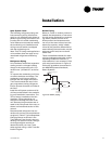
Location Considerations
Selecting the appropriate location for
installing a unit is very important. The
following factors should be consid
-
ered:
1 Floor design must have sufficient
structure to withstand the weight
of the unit while allowing for
openings in the floor for a return
air duct, electrical and piping sup
-
ply lines fed through the floor. See
page 7 for unit weights.
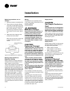
2 Wall space design should allow the
unit to be mounted to the wall se
-
curely. The wall surface behind
the unit should be smooth and lev-
el. Wall and floor moldings should
be removed prior to installation. A
wall slightly out of level may cause
problems with unconditioned air
leaking into the room. Remove
any object projecting more then
1/8” (.3175cm) from the wall sur-
face. Note: Additional gasket or
furr strips may be installed to ac-
commodate for an uneven wall.
3 There are two removable knock-
outs in the rear of the unit, on ei
-
ther end, for piping and electrical
supply lines. A pipe chase is locat
-
ed in the upper back portion of the
unit for crossover piping. The out-
side air opening is located in the
lower back of the unit and the path
to the wallbox on the outside wall
should be unobstructed.
4 The physical layout of the room
should accommodate any accesso-
ries ordered with the unit. Condi-
tioned air is distributed through
the grille on top of the unit and re-
turned through the return air grille
on the bottom of the unit. Avoid
placing any objects that may ob
-
struct either grille or interfere with
airflow.
5 Internal access to the unit is pro-
vided by the removable front pan-
el. Sufficient space should be
allowed to lift the panel for mainte
-
nance purposes.
6 Ensure the floor surface is level.
Note: The unit leveling legs can be
adjusted to accommodate slight
out-of-level installation surfaces.
Unit Mounting
Note: All wall intake boxes should be
installed prior to mounting the unit
ventilator. Refer to Page 14 for wall
box installation instructions.
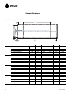
The 1/2” mounting or anchoring holes
are located on the back of the unit on
each end. See Figures 3.
Note: All mounting fasteners are to be
provided by the installer.
Installation