


6 UV-SVN03D-EN
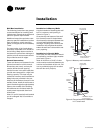
OA/RA Actuator (Option)
The OA/RA actuator provides true
spring return operation for positive
close-off of the OA/RA damper. The
spring return system of the actuator
closes the outside damper if power is
lost to the building. When ordered
with factory controls, the actuator is a
3-point floating design. A 2 to 10 VDC
actuator is available when other than
Trane controls are specified. See Table
1 for OA/RA technical data.
Note: Because the damper actuator is
a spring return type an inner spring
will close the damper upon loss of
power. If the need to service or replace
the actuator is required, the spring
must be "loaded" for the damper to
function properly. The term loaded
means that the blade must be held in
the return air position upon replace
-
ment of the actuator.
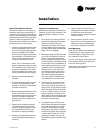
Face and Bypass Actuator (Option)
The face and bypass damper actuator
incorporates a direct couple design. It
provides electronic protection against
overload. A limit switch is not includ
-
ed, nor required as part of the design.
When reaching the damper end posi-
tion, the actuator automatically stops.
The gears can be manually disen
-
gaged with a button on the housing.
See Table 2 for face and bypass actua
-
tor specifications.
Modulating Water Valves (Option)
The modulating control valve provides
optimum control of hot and chilled wa
-
ter flow in various heating and cooling
applications. They are designed to
provide sinusoidal valve actuator trav
-
el and operate silently, resisting water
hammer.
The actuator on the valve is a 24V, 3-
point floating type. See Table 3 for
modulating water valve specifications.
Isolation Valve (Option)
The isolation valve is a two position
24V, spring return type valve. It pro
-
vides added control in heating and
cooling applications when used in
conjunction with the face and bypass
damper.
Table 1: OA/RA actuator specification
Table 3: Mod. water valve specification.
Power Supply
24 VAC ± 20% 50/60 HZ
24 VAC ± 10%
Power
Consumption
Running: 2.5 W
Holding: 1 W
Transformer
Sizing
5 VA (class 2-power source)
Overload
Protection
Electronic throughout 0 to
95-degree rotation
Control Signal 2 to 10 VDC
3-point floating with Trane controls
Angle of
Rotation
Maximum 95-degree
Adjustable with mechanical stop
Torque 35-inch/lb
Direction of
Rotation
Spring return reversible with CW/
CCW mounting
Position
Indication
Visual indicator, 0 to 95-degrees
Run Time
(nominal)
90-second constant (independent of
load)
Noise Level Running: 30 dB
Power Supply
24 VAC - 50/60 HZ
Power
Consumption
4 W
Max. Duty Cycle 15%
Nominal Timing 120 sec.
Operating Ambient
Temp.
0 to 65°C
32 to 150°F
Min./Max. Fluid Temp. 1 to 95°C
34 to 203°F
Operating Pressure
Differential
Max. - 4 bar (60 psi)
Pressure Rating Static - 20 bar (300 psi)
Burst - 100 bar (1500 psi)
Flow Characteristic Linear
Table 2: Face-bypass actuator specification
Table 4: Isolation valve specification.
Power Supply
24 VAC ± 20% 50/60 HZ
24 VAC ± 10%
Power
Consumption
2 W
Transformer
Sizing
3 VA (class 2-power source)
Angle of
Rotation
Maximum 95-degree
Adjustable with mechanical stop
Torque 35-inch/lb
Direction of
Rotation
Reversible with switch L/R
Position
Indication
Clip-on indicator
Run Time
(nominal)
90-second constant
Manual
Override
External push button
Noise Level Less than 35 dB
Control Signal 3-point floating
Power Supply
24 VAC - 50/60 HZ
Power
Consumption
5 W
Max. Fluid Temp. 94°C
200°F
Min. Fluid Temp. 1°C
34°F
Max. Operating Pressure 300 psi
Max. Close-off Pressure 1/2" = 30 psi
3/4" = 20 psi
1" = 15 psi
General
Information
On heating coils, and two-pipe changeover applications, the valve is normally
open to help prevent the coil from freezing in-case of power loss.
For cooling, the valve is normally closed and opens when there is a call for cool-
ing. See Table 4 for isolation valve specifications.