


UV-SVN03D-EN 21
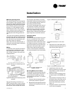
Manually Opening Valve
The manual opener can be manipulat-
ed only when in the up position. The A
port can be manually opened by firmly
pushing the white manual lever down
to the midway position and pushing
the lever in. In this position, both A
and B ports are open. This “manual
open” position may be used for filling,
venting and draining the system or
opening the valve during power fail
-
ure.
The valve can be closed by depressing
the white lever lightly and then pulling
the lever outward. The valve and actu-
ator will return to the automatic posi-
tion when power is restored.
Note: If the valve is powered open, it
cannot be manually closed, unless the
actuator is removed.
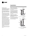
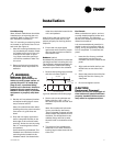
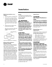
Wiring
A controller and a separate transform-
er is required to operate each valve.
See Figures 9 and 10. Port A “open”
and “closed” denote valve open and
closed positions.
Figure 9: Wiring for modulating valve
actuator
Figure 10: Wiring for modulating valve
actuator
The typical floating controller is an
SPDT controller with a center-off posi
-
tion. On a change in temperature from
the set point, the controller will close
the normally open (NO) or normally
closed (NC) contacts, driving the valve
to an intermediate position until a fur
-
ther change at the controller.
The valve is set between the limits of
the controller to satisfy various load
requirements. In the event of power
failure, the valve will stay in the posi
-
tion it was in before loss of power.
When power is restored, the valve will
again respond to controller demand.
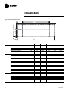
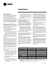
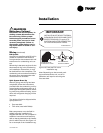
Isolation Valves
Installation
The valve can be mounted in any posi-
tion on a vertical line. If the valve is
mounted horizontally, the actuator
must be even with or above the center
line. Make sure there is enough room
to remove actuator cover for servicing.
Mount the valve on the tube or pipe.
Note: Ensure the flow through the
valve is in the direction indicated by
the arrow stamped on the valve body.
Figure 11: Proper mounting for
isolation valves.
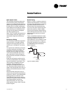
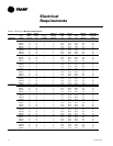
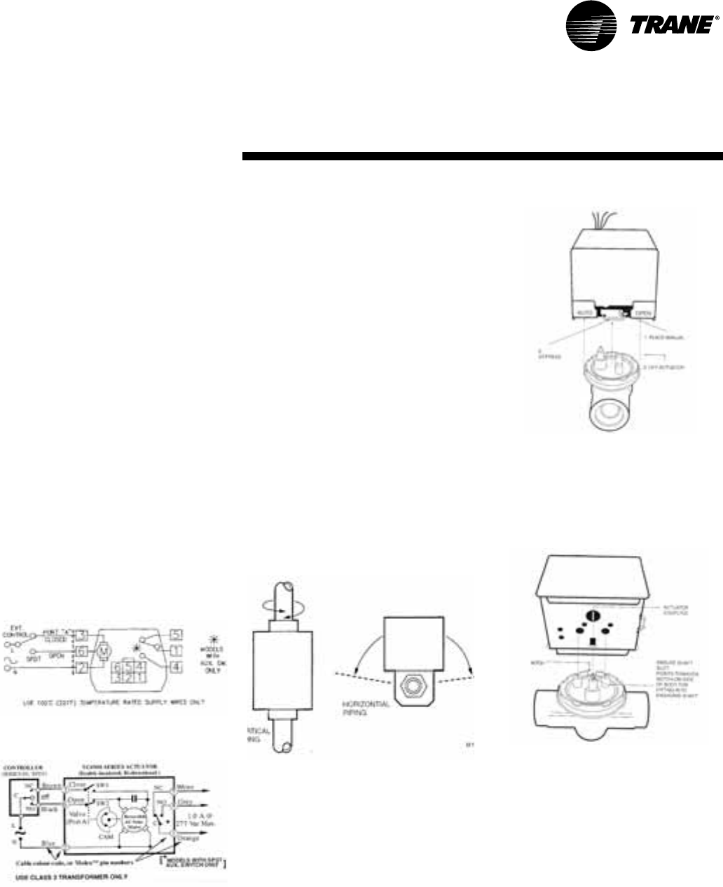
Servicing/Removal of Valves
The actuator can be removed from the
valve body. Removing the actuator is
recommended if soldering is being
conducted near the valve. To remove
the actuator:
1 Place the manual operating lever
to the Open position, Figure 12
2 Depress the locking button and lift
actuator until it separates from the
valve body.
Figure 12: Removing valve actuator
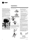
To install the actuator to the valve
body:
3 Align the slot on the shaft of the
valve with the valve body notch on
side of body. See Figure 13.
Figure 13: Installing isolation valve
4 Install body valve into pipe.
5 Wiring connections may be made
either before or after actuator in-
stalled on body.
6 Place the manual operating lever
on the actuator in the OPEN posi-
tion.
7 Align actuator coupling to slot on
the shaft of the valve body and fit
the head onto the valve body to
ensure the shaft seats correctly,
Figure 11.
8 Press the actuator and valve body
until it secures together.
Installation