28 UV-SVN03D-EN
WARNING
Hazardous Service
Procedures!
The maintenance and trouble-
shooting procedures recommend-
ed in this section of the manual
could result in exposure to electri
-
cal, mechanical or other potential
safety hazards. Always refer to
the safety warnings provided
throughout this manual concern
-
ing these procedures. When possi-
ble, disconnect all electrical
power including remote discon-
nects before servicing. Follow
proper lockout/tagout procedures
to ensure the power can not be in
-
advertently energized. When nec-
essary to work with live electrical
components, have a qualified li-
censed electrician or other indi-
vidual who has been trained in
handling live electrical compo-
nents perform these tasks. Failure
to follow all of the recommended
safety warnings provided, could
result in death or serious injury.
Access to Fanboard & Motor
The unit ventilator fan board can be re-
moved for service to the blower motor
and fan wheels. The fan board must
also be removed for easier access to
the unit coils for cleaning and mainte
-
nance. Utilize the following steps for
proper removal of the fanboard.
1 Turn off power to the unit and re-
move the front panel.
2 Disconnect P-trap from drain pan.
3 Disconnect fan plug.
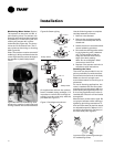
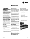
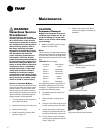
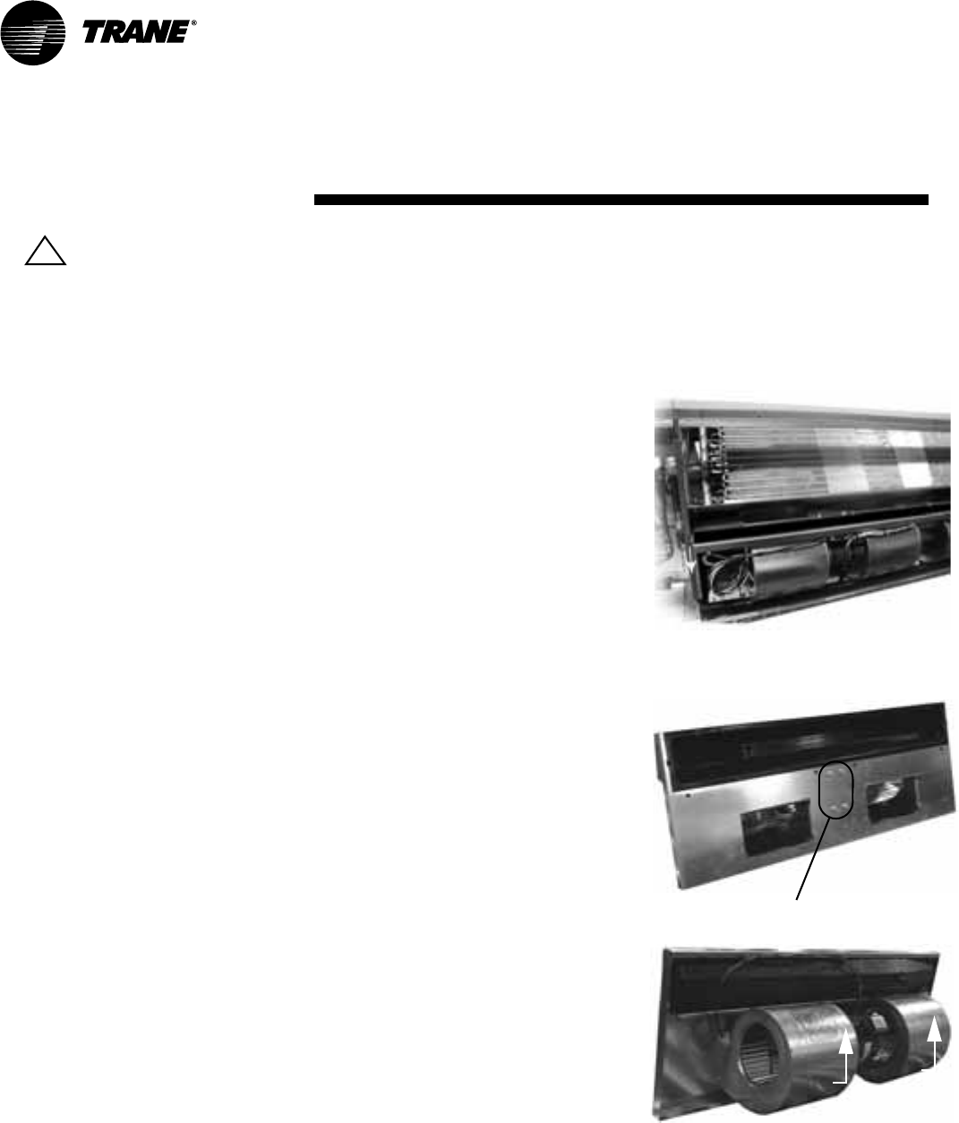
4 Slide fan board by pulling deck
forward, Figure 17.
CAUTION
Equipment Damage!
Support the fanboard to prevent
the deck from sliding too far for
-
ward and falling out of the unit.
Failure to do so may cause equip-
ment damage.
5 When reinstalling, use the same
steps in reverse order.
Motor
The fan motor is a permanent split ca-
pacitor type motor with voltage specif-
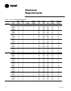
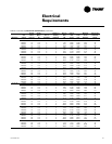
ic power. See Table E1 through E3 for
electrical performance and motor volt
-
age.
Table E3: Motor Voltage
If a replacement motor is required, it
should be ordered from The Trane
Company. To replace the fan motor,
complete the following steps:
6 Complete steps for removal of
fan board.
7 Disconnect the motor ground
wire.
8 Using a 7/16” Allen wrench, loos-
en the coupling on the fan shaft.
9 Loosen the screw on the motor
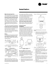
clamp until it allow the motor to
be lifted off the base, Figure 18.
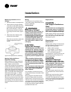
10 Lift the motor and pull forward
until fan shaft separates from the
motor, Figure 19.
Unit Voltage Motor Voltage
115-60-1 115-60-1
208-60-1 208/230-60-1
230-60-1 208/230-60-1
208-60-3 208/230-60-1
460-60-3 265-60-1
265-60-1 265-60-1
230-60-3 208/230-60-1
11 Attach new motor to fan shaft
and reverse steps to complete in
-
stallation.
Maintenance
!
Figure 17: Fan board removal for fan/
motor access
Figure 18: Loosen screws
Figure 19: Lift/pull motor forward


