


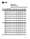
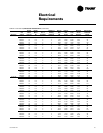
20 UV-SVN03D-EN
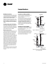
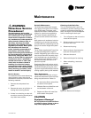
Modulating Water Valves (Option)
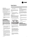
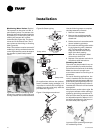
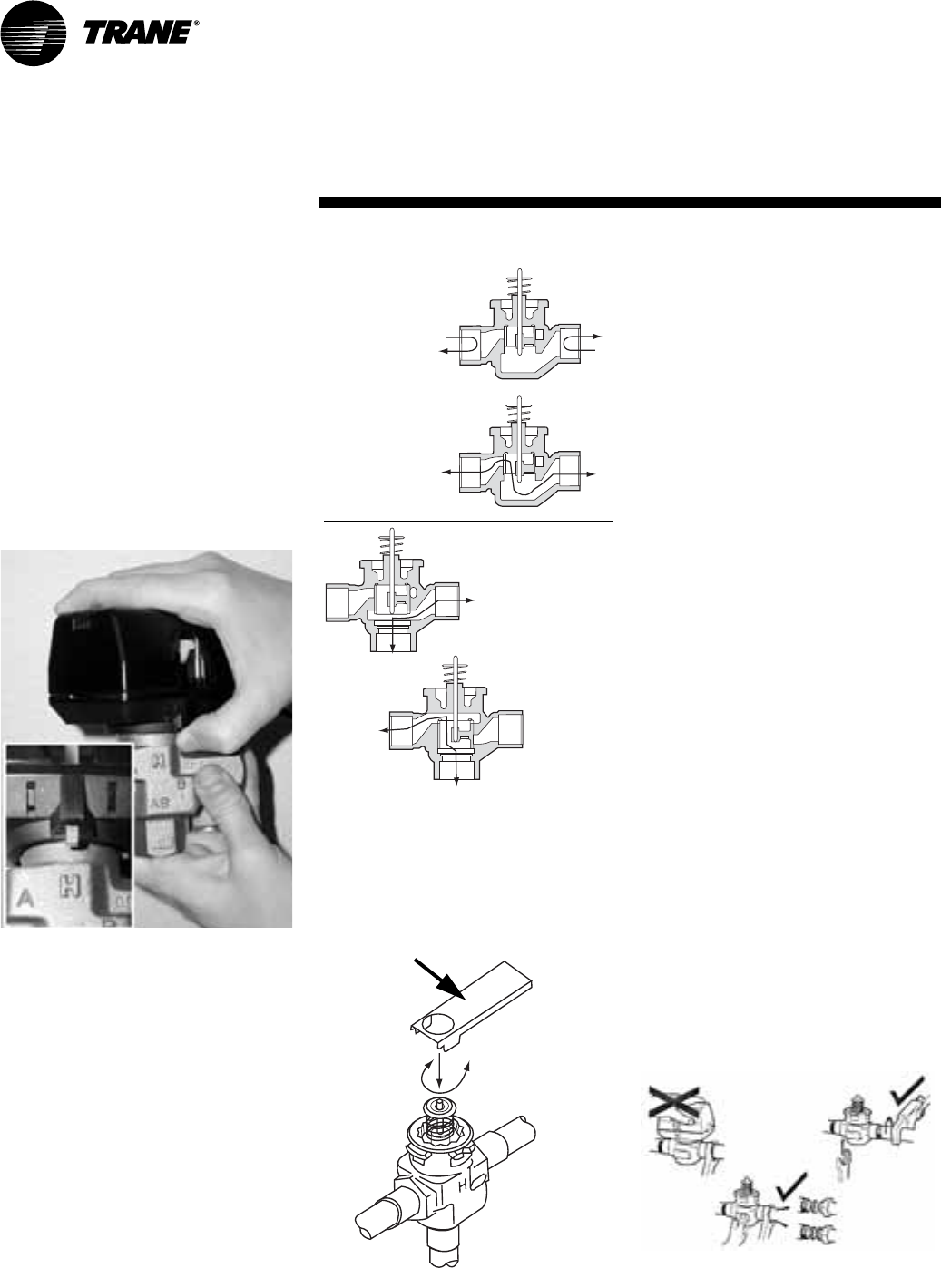
The actuator on the valve is a 24V, 3-
point floating valve. The actuator can
be easily removed from the valve body
by pressing in on the locking tab and
rotating the actuator 45° counter-
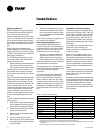
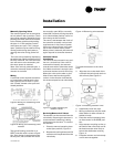
clockwise (See Figure 6a). The 2-way
valves are bi-directional flow. The 3-
way valves can be mixing or diverting
(See Figure 6b).
Note: The actuator must be removed if
soldering is being conducted near the
valve. High heat may cause damage to
the actuator’s plastic body/mecha
-
nisms.
Figure 6a: Remove modulating valve
actuator by pressing in tab (inset) and
turning actuator 45° counterclockwise.
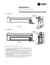
Figure 6b: Steam piping
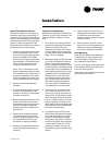
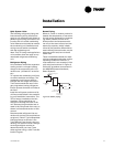
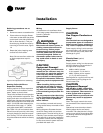
On applications without the optional,
factory installed piping packages, it is
important to remove the cartridge as
-
sembly from the valve body with the
provided tool (Figure 7).
Figure 7: Cartridge removal tool
Closed
Open
A
B
A
B
AB<->B
AB
B
AB<->A
A
AB
2-way valve
3-way valve
Use the following steps to complete
cartridge assembly removal:
1 Remove valve actuator.
2 Remove the cartridge assembly
from the valve body with the en-
closed tool.
3 Solder the valve in accordance with
normal soldering practices.
4 Re-install the cartridge after solder-
ing by tightening until it bottoms
out. The top surface of the car-
tridge will be flush with the top
edge of the body casting.
Note: Do not overtighten. Maxi-
mum torque is 40 in-lb.
5 Replace valve actuator and wire in
accordance with instructions.
Plumbing the Valve
The valve may be plumbed in any an-
gle but preferably not with the actua-
tor below horizontal level of the body.
Make sure there is enough room
around the actuator for servicing or re
-
placement.
For use in diverting applications, the
valve is installed with the flow water
entering through the bottom AB port
and diverting through end ports A or
B. In mixing applications the valve is
installed with inlet to A or B and outlet
through AB.
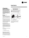
Mount directly to the tube or pipe. Do
not grip the actuator while making or
tightening plumbing connections. Ei
-
ther hold valve body by hand or attach
an adjustable spanner (38mm/1-1/2”)
across the hexagonal or flat faces on
the valve body. See Figure 8.
Figure 8: Proper plumbing technique
for modulating valves
Installation