


OM/SM-HY-6G(CE) 27
OM/SM-HY-6G(CE)
27
terminals from the igniter module. Be careful not to
pull the terminal by the wire. Use needle nose pliers
to grip onto the terminal itself.
5. Remove the screws that secure the igniter manifold.
6. Remove the igniter module.
To Install:
7. Position the new igniter against the back wall of the
electrical compartment.
8. When all four screws are partially threaded, tighten
them one at a time.
9. Plug in each of the terminals. Double check to
ensure that they are in the correct location.
10.14 Pilot Switch (SW3) Removal
P/N 087951
1. Shut off the power supply. Disconnect the four color
coded wires from the switch assembly.
2. The switch snaps into the metal plate where it is
retained by plastic tabs on the top and bottom. To
remove the switch from the plate, press in on both
tabs at the same time and slide the switch out of the
bracket hole.
To replace the switch
3. Insert the new switch into the bracket hole until its
tabs clear the hole and snap into position.
4. Reattach the wires to the switch.
10.15 Pilot Burner Replacement/Current Check/
Adjustment - Pilot Flame Sensor
Replacement
P/N 123641)
P/N 003328 Flame Sensor
1. Turn off the main gas and power supply.
2. Remove the front cover.
3. Remove the right side panel as described in
Paragraph 10.2.
4. Turn the manual gas valve to the OFF position. Turn
the pilot switch to the OFF position.
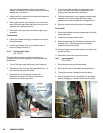
5. Disconnect the pilot line from the pilot burner.
6. Disconnect the “spark” lead from the pilot burner.
7. Remove the flame sensor from the flame sensor
bracket.
8. Remove the pilot burner.
Installation:
9. Connect the pilot line to the pilot burner.
10. Connect the “spark” lead to the pilot burner. Be sure
to route the lead around the outside of the gas lines.
11. Replace the flame sensor on the flame sensor
bracket.
12. Apply anti-seize lubricant to mounting head screw
threads. Install the pilot burner and flame sensor
assembly, and tighten the screws.
NOTE: Route the “spark” lead and flame sensor wire
away from the manifold to prevent improper
operation.
13. Turn manual gas valve to the ON position.
14. Connect unit to the branch circuit and turn on the
main gas supply.
15. Place pilot switch SW3 in the ON position. Check for
gas soundness.
Pilot Flame Current Check
WARNING
WHEN STEAMER POWER IS TURNED ON, THERE IS
HIGH VOLTAGE PRESENT IN THE ELECTRICAL
COMPONENTS COMPARTMENT. BE SURE THAT
STEAMER IS DISCONNECTED FROM BRANCH
CIRCUIT BEFORE PERFORMING ANY REPAIRS.
1. Turn off steamer power.
2. Disconnect the ground (green) wire from the igniter
module.
3. Connect a DC micrometer between the igniter
ground terminal and the disconnected green wire.