


28 OM/SM-HY-6G(CE)
OM/SM-HY-6G(CE)
28
WARNING
DO NOT ATTEMPT TO LIGHT THE PILOT BURNER
WITH A FLAME.
4. Ignite the pilot. The micrometer should read 3
microamps minimum.
• If current reading is correct, replace the igniter
module (see 10.13).
• If current reading is below 3 microamps,
continually check the Flame Rectification Circuit
(large orange wire, spark electrode, pilot burner
hood, and ground connections). If necessary,
tighten ground connections and/or replace
defective component(s).
5. Check for moisture around the pilot burner, and for
corrosion on the electrode and the pilot burner hood.
If necessary, remove moisture with a dry, clean
cloth. If hood and/or electrode are excessively
corroded, replace pilot burner assembly.
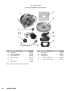
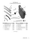
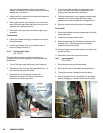
10.16 Steam Generator Gas Jet Manifolds
P/N 123704 and 123705
1. Shut-off power and gas to the steamer.
2. Remove the right side panel.
3. Turn manual gas valve to the closed position.
4. Remove the four aluminum tubes connected to the
manifolds. Disconnect using an open ended wrench.
5. Disconnect all wire connections to the pilot.
6. Remove the two screws from the pilot mounting
bracket. Remove pilot from the gas manifold.
7. Using a wrench, remove the two top and one bottom
bolts which hold the manifold to the steam generator
manifold mounting bracket.
8. Remove the screws in the heat shield.
9. Remove the burner manifold from the appliance.
10. Remove the flame retention springs and injectors as
required.
To Reassemble:
11. Replace the injectors and retention springs. Ensure a
suitable gas sealant is used on the threads of the
injectors to ensure a gas tight seal
12. Fit the burner manifold to the steam generator
manifold mounting bracket.
13. Reinstall and tighten the aluminum tubes to the
burner manifold.
NOTE: Ensure all gas connections are sound before
continuing.
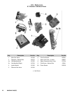
10.17 Timer Assembly Timer Fastener Nut
P/N 100983 P/N 101145
1. Remove the three hex nuts which retain the control
panel cover. Remove the cover.
2. Remove the knob from the timer. Under the knob is
a hexagonal nut which holds the time mechanism to
the steamer. Note that there is a flat on the timer
shaft which corresponds to a frictional mounting hole
on the knob.
3. From the left side, unplug the five terminals/wires
(violet, gray, black, tan and white) from the timer
mechanism and unplug the two black timer motor
leads.
4. With an open-ended wrench, remove the hex nut
holding the timer in place. The timer may then be
removed from inside the compartment.
NOTE: Right below the timer shaft, the timer has a small
plastic disk molded onto the case. There is a
corresponding hole punched into the front panel. This
hole may be seen from the inside of the compartment
only when the timer is removed.
To Install:
5. Fit the timer in place making sure that it is properly
placed so that the disk on the timer fits into the
punched hole in the front panel.
6. Once the timer is properly located, tighten the hex
nut so that the timer does not slip or rotate. Do not
over-tighten the nut.
7. Align the flat of the knob hole with the flat on the
timer shaft. Press the knob firmly onto the timer
shaft.
8. Plug in the wires identified above and connect the
two black wires from the motor leads.
9. Reattach the control panel cover.