


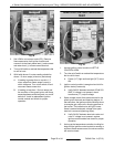
A. Verify 120VAC between T8 and ground. If
correct, output from controller is functioning
properly.
B. If incorrect, install a replacement
temperature controller and check for proper
operation.
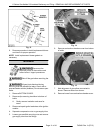
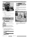
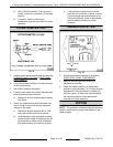
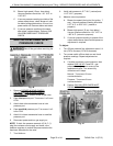
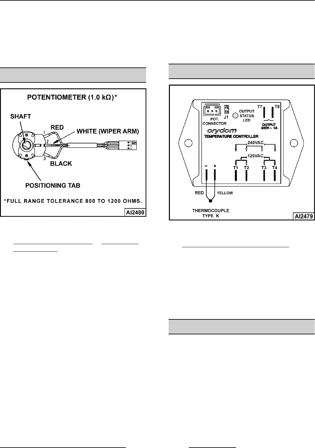
POTENTIOMETER TEST
Fig. 34
1. Access control panel potentiometer by removing
CORNER PANEL (TILTING) or SIDE PANEL
(STATIONARY).
2. Turn potentiometer shaft fully counterclockwise
to the lowest setting.
3. Set VOM to measure resistance.
4. Connect meter leads to the white and black lead
wires on potentiometer terminals.
A. Resistance should measure approximately
zero ohms.
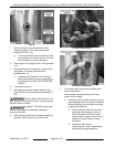
5. Slowly turn potentiometer shaft clockwise over
the full range of travel and monitor resistance
change on the meter.
A. Resistance should measure 800 to 1200
ohms with shaft turned fully clockwise.
B. If the resistance value increased smoothly
without sudden drops or spikes and the full
travel resistance value is within tolerance
then potentiometer is functioning properly.
C. If the resistance value did not increase
smoothly but had drops or spikes over the
full travel range then potentiometer is not
functioning properly. Install a replacement
potentiometer and check for proper
operation.
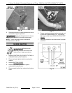
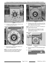
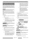
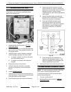
THERMOCOUPLE TEST
Fig. 35
1. Access temperature controller as outlined in
ELECTRICAL PANEL COMPONENTS.
2. Remove thermocouple lead wires from
temperature controller.
3. Check the thermocouple for a measurable
resistance (approximately 5 to 10 ohms at room
temperature). If meter reads an overload (OL)
condition (open), or zero ohms (short) replace
the thermocouple and check temperature
controller for proper operation.
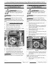
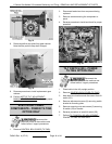
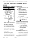
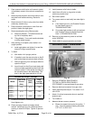
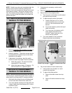
VENTING
NOTE: This procedure outlines venting the reservoir
jacket to remove air for proper heat transfer to the
kettle contents.
K Series Gas Kettles 2/3 Jacketed Stationary and Tilting - SERVICE PROCEDURES AND ADJUSTMENTS
Page 19 of 44 F45461 Rev. A (0713)