SEQUENCE OF OPERATION
(POWER TILTING OPTION)
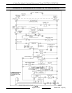
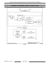
Refer to schematic diagram AI3538 for power tilting
option and AI3537 for the main control circuit diagram
that includes Tilt Switch (2S) and Raise-Enable relay
(K3).
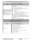
1. Conditions.
A. 120VAC to kettle, polarity is correct, and is
properly grounded.
B. Power switch off.
C. Tilt motor switch off (center position).
D. Kettle in the upright position.
E. Tilt switch (2S) operated, N.O. contacts held
closed (kettle arm engages switch actuator).
F. K3 raise-enable relay N.O. contacts are
open (raise-enable relay coil is de-
energized).
G. Down limit switch N.C. contacts closed.
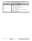
2. Power switch on.
A. Power light (1LT) (amber) comes on.
B. 120/24VAC transformer (2T) energized.
Power to tilt motor switch common terminal.
NOTE: If the temperature dial is set to call for heat,
the ignition trial starts and module begins sparking at
ignitor.
3. Operate tilt motor switch to tilt the kettle
(momentary on - tilt).
A. K2 down relay coil is energized through
down limit switch N.C. contacts.
1) K2 4/7 N.O. contacts close.
2) K2 9/6 N.O. contacts close.
3) K2 8/5 N.O. contacts close.
B. 120VAC to DC tilt motor controller through
K2 4/7 N.O. contacts.
1) 90VDC output is activated at terminals
A + (positive) and A - (negative). DC tilt
motor powered through K2 9/6 N.O.
contacts, K2 8/5 N.O. contacts and
kettle tilts.
C. Kettle tilted approximately 10° and tilt switch
(2S) is un-operated (kettle arm disengages
from switch actuator). 2S contacts change
position from N.O. to N.C.
1) With 2S N.O. contacts open - power is
removed from control circuit and
heating stops.
2) With 2S N.C. contacts closed - Raise
enable-relay coil (K3) is energized and
K3 N.O. contacts close. No power is
transferred to K1 up relay until tilt motor
switch is operated to raise the kettle.
4. Kettle reaches full tilt position at approximately
95° and the down limit switch is operated. The
down limit switch N.C. contacts open and K2
relay coil is de-energized.
A. The three sets of K2 N.O. contacts return to
the open position. Power is removed from
the DC motor controller, the DC tilt motor
and kettle travel stops.
5. Operate tilt motor switch to return the kettle
upright (momentary on - raise).
A. K1 up relay coil is energized through raise-
enable (K3) closed contacts.
1) K1 4/7 N.O. contacts close.
2) K1 9/6 N.O. contacts close.
3) K1 8/5 N.O. contacts close.
B. 120VAC to DC tilt motor controller through
K1 4/7 N.O. contacts.
1) 90VDC output is activated at terminals
A + (positive) and A - (negative). DC tilt
motor powered through K1 9/6 N.O.
contacts, K1 8/5 N.O. contacts and
kettle raises.
2) After the kettle leaves full tilt position,
the down limit switch is un-operated
and the switch contacts return to N.C.
position. The direction of kettle travel
can then be reversed (if needed) by tilt
motor switch.
6. Kettle reaches full upright position, the tilt switch
(2S) is operated (kettle arm engages switch
actuator). 2S contacts change position from N.C.
to back to N.O.
A. With 2S N.O. contacts closed - power
restored to control circuit and heating
resumes.
B. With 2S N.C. contacts open - Raise enable-
relay coil (K3) is de-energized and K3 N.O.
contacts open. K1 up relay coil is de-
energized.
K Series Gas Kettles 2/3 Jacketed Stationary and Tilting - ELECTRICAL OPERATION
Page 37 of 44 F45461 Rev. A (0713)


