


E. Tilt switch (2S) operated, N.O. contacts held
closed (kettle in the full upright position -
tilting models only).
F. Pressure switch (1PAS) N.C. contacts are
closed.
G. Temperature dial at lowest setting
(potentiometer fully CCW).
1) Internal relay N.O. contacts are open.
H. Kettle at room temperature.
2. Power switch ON.
A. Power provided to the power tilt circuit
(kettels with power tilt option only).
B. Power light (1LT) (amber) comes on.
C. 120VAC to water level controller through tilt
switch (2S) N.O. contacts, held closed
(tilting models only) and pressure switch
(1PAS) N.C. contacts.
3. Water level control (WLC) energized.
A. WLC LLCO probe satisfied (fluid in kettle
reservoir jacket at proper level).
1) LLCO LED comes on.
B. WLC LLCO N.C. contacts open. Low water
light (2LT) (red) remains off.
C. WLC LLCO N.O. contacts close.
1) 120VAC to temperature controller.
4. Set the temperature dial to call for heat (warm/
simmer/boil).
A. 120VAC output from T8 on temperature
controller.
1) Heat light (3LT) (amber) comes on.
2) Blower motor (1MOT) energized.
3) 120/24VAC transformer (1T) primary
energized.
5. 24VAC is output from transformer (1T)
secondary to heating circuit.
A. Gas shut-Off Valve (1SOL) energized (tilting
models only).
B. Delay on make timer (1TMR) is energized
and begins 15 second count down before
output from timer is turned on (will energize
relay K4).
NOTE: Relay K4 contacts provide the 24VAC input
voltage signal to the blower speed control to select
blower motor speed (low or high). The blower speed
control (J6.4) sends a corresponding 24VDC pulse
width modulation (PWM) output signal to the blower
motor for low or high speed operation.
C. Blower speed control powered at connector
J5.4 for blower motor low speed operation
through K4 N.C. contacts. Blower at low
speed.
D. Ignition module energized and trial for
ignition begins. The module generates
spark at ignitor and energizes the dual gas
valve coils to open the valves and provide
gas for the gas/air mixture to light the
burner.
E. Burner lights and kettle heating begins. As
long as the ignition control module senses a
burner flame, the ignition module will
continue to power the gas valve.
1) If burner flame is not sensed within 7
seconds, ignition module stops
sparking, de-energizes gas valve coils
and enters lockout mode.
2) If lockout, ignition fail light (4LT) (red)
comes on.
F. Time expires on delay on make timer
(1TMR). Timer output turns on and relay K4
is energized.
1) K4 N.C. contacts open and remove
power from blower speed control at
connector J5.4 (low speed blower
operation).
2) K4 N.O. contacts close and apply
power to blower speed control at
connector J5.3 (high speed blower
operation). Blower at high speed.
6. Kettle heat cycles with the temperature
controller.
7. On tilting models only, when kettle is tilted to
empty contents the tilt switch (2S) N.O. contacts
open to remove power from control circuit. Tilt
switch (2S) contacts will close when the kettle is
returned to full upright position and resume
normal operation.
A. Power light (1LT) (amber) remains on.
8. Kettle heating will continue to cycle with the
temperature controller until the temperature dial
is turned fully CCW or power switch is turned
OFF.
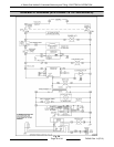
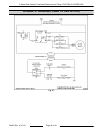
K Series Gas Kettles 2/3 Jacketed Stationary and Tilting - ELECTRICAL OPERATION
F45461 Rev. A (0713) Page 36 of 44