


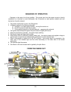
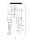
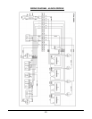
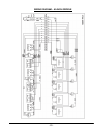
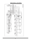
SEQUENCE OF OPERATION
Operation is the same for all size griddles. The neutral wire from the power source is directly
connected to a terminal on each thermostat, the N terminal on each ignition module and one
terminal on the pilot solenoid.
1. The power on/off switch is set to the ON position.
2. Voltage is applied to the following terminals
A. Terminal L1 on each igniter module – turning the module on
B. The NO terminal of each flame switch
C. The remaining terminal on the pilot solenoid – energizing the solenoid
3. The igniter electrode sparks against the pilot head and lights pilot burner
4. When the pilot flame is sensed – the igniter stops sparking
5. Pilot burner heats up flame switch sensor
6. When flame switch is sufficiently heated (cherry red) – the switch closes and supplies voltage to
one terminal on each burner solenoid and one terminal on each indicator light
7. When a thermostat is rotated out of the OFF position – the neutral return is connected to the
other side of the indicator light and the other terminal(s) on the other side of the burner
solenoid(s)
8. The indicator light illuminates
9. Gas flows to the main burners and is ignited by the pilot flame.
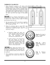
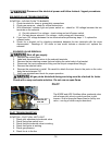
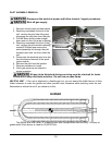
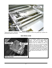
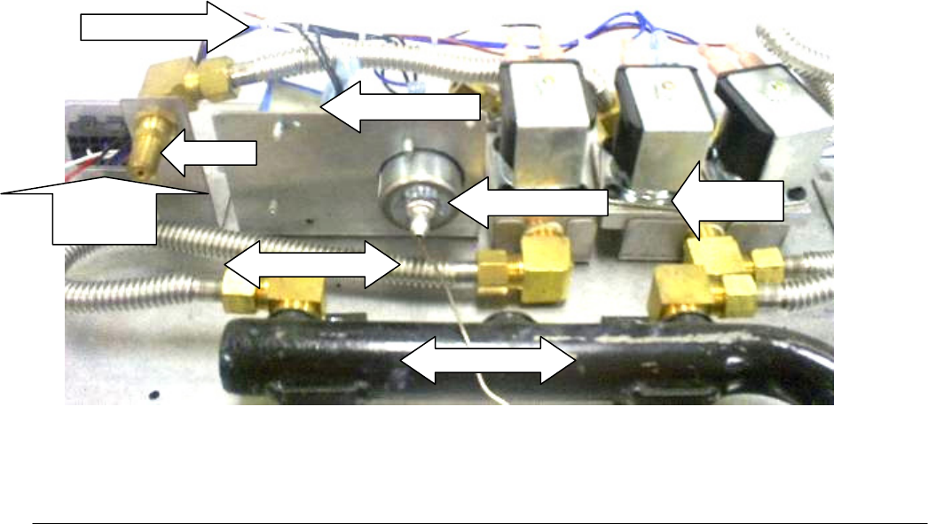
FROM THE INSIDE OUT
WIRE HARNESS
SPARK IGNITOR
ORIFICE
HARNESS
CONNECTOR
SOLENOID
VALVE
FLAME SWITCH
3/8” FLEX TUBE
MANIFOLD PIPE
-
19 -