


Disconnect the electrical power and follow lockout / tagout procedures
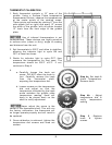
THERMOSTAT TROUBLESHOOTING
SYMPTOM – NO POWER TO THE BURNER SOLENOID
1. Check for loose or excessively greasy/dirty connections at terminals
2. Check for continuity/resistance between the two thermostat terminals with wires disconnected
A. If you get continuity/resistance with the thermostat off or open – replace thermostat
B. If you do not get continuity or resistance with thermostat on or closed – replace
thermostat
3. Check flame switch for continuity/resistance and voltage
4. Check for voltage from hot line
A. If no voltage check wiring for shorts or breaks
SYMPTOM – GRIDDLE SURFACE TEMPERATURE IS MORE THAN ±15°F OF THERMOSTAT SET
POINT
1. Ensure that you are using a high quality, calibrated surface temperature measuring device.
A. Do not use an infrared thermometer – these are highly inaccurate on a griddle plate.
B. Refer to instructions on the proceeding page for proper placement of probe and method.
2. Check that burners are properly adjusted.
3. Check that burner valves are operating correctly.
4. Check that there are no burner orifice obstructions
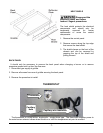
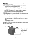
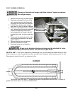
5. Check that thermostat capillary bulb is completely seated back as far as possible in the groove
on the bottom of the plate. No part of the bulb should be exposed from behind the bulb heat
shield.
6. Check that the high temp. capillary wire insulation is completely covering capillary wire from the
connection at the thermostat to the beginning of the bulb and that the insulation is not damaged
or burned thru. If insulation appears damaged – replace the insulation.
7. If you have found no problems in steps 1 – 6, proceed to the next page for calibration
instructions.
8. If thermostat will not calibrate after all previous steps – replace thermostat.
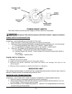
THERMOSTAT REMOVAL
1. Remove the control panel
2. Remove the knob
3. Label and disconnect the wires
4. Remove the two screws and two washers securing the thermostat dial and thermostat to the
Control panel.
5. Remove the heat shield.
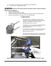
6. Pull the capillary bulb straight out from the plate groove.
7. Reverse the procedure to install while ensuring that capillary bulb is completely seated – all the
way to the back of the plate groove.
8. Check that capillary wire is completely covered with insulation from the connection at the
thermostat to the beginning of the sensor bulb.
-
8 -