V SERIES HOLDING, TRANSPORT & PROOFING CABINET F-41190 (09-10)
5
electrician. Do not remove the
grounding prong from this plug.
Verify that the power source
matches the Serial Data Plate located
on the lower back corner of the
cabinet and the plug configuration
before the connection is made.
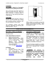
(Fig.4)
(Fig. 4)
OPERATION
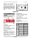
CONTROLS
The Cabinet and its parts
are hot. Be very careful when operating,
cleaning, or servicing the cabinet.
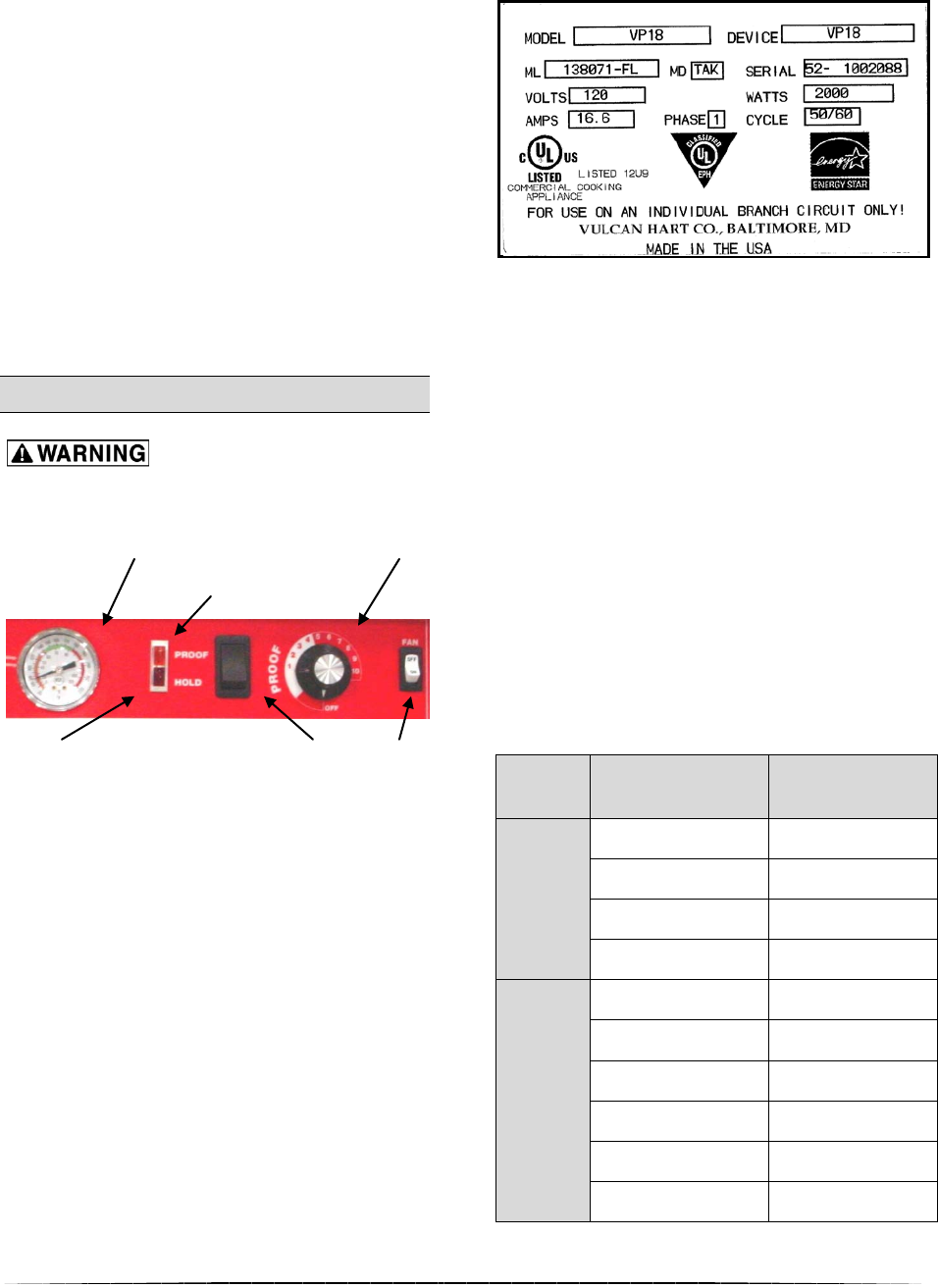
THERMOMETER PROOF THERMOSTAT
INDICATOR
LIGHT
HOLD PROOF / HOLD SWITCH
FAN
INDICATOR ON/OFF
LIGHT SWITCH
Thermometer:
The Thermometer indicates the interior
temperature of the cabinet.
Proof Indicator Light:
The Proof Indicator Light indicates
power is supplied to the cabinet and the
cabinet is in Proofing Mode.
Thermostat:
The Thermostat turns power on to the
heating elements. If “Proofing mode” is
desired, the thermostat should be set in
the white “Proof” area (1 through 4.) If
“Holding mode” is desired, the
thermostat should be set in the red area
(5 through 10.) (Fig. 5)
Hold Indicator Light:
The Hold Indicator Light indicates power
is supplied to the cabinet and the
cabinet is in Holding Mode.
Proof / Hold Switch:
Flip the switch upward for Proofing
mode or flip the switch downward for
Holding mode.
Fan On/Off Switch:
The Fan On/Off Switch turns the fan on
or off only.
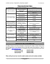
Mode
Thermostat
Setting
Approximate
Temperature
PROOF
1 100⁰F (37⁰C)
2 110⁰F (43⁰C)
3 120⁰F (49⁰C)
4 130⁰F (54⁰C)
HOLD
5 140⁰F (60⁰C)
6 150⁰F (66⁰C)
7 160⁰F (71⁰C)
8 170⁰F (77⁰C)
9 180⁰F (82⁰C)
10 190⁰F (88⁰C)
(Fig.5)


