


Endurance
Page 13
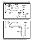
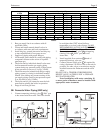
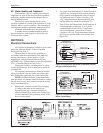
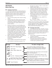
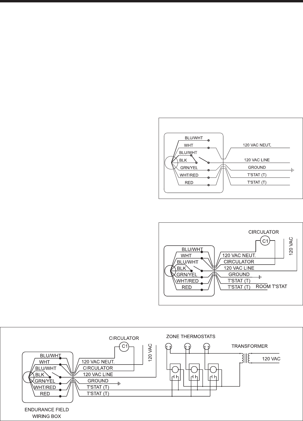
Figure 20. Single Zone With Room Thermostat (internal
pump provides system flow).
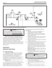
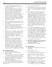
Figure 21. Single Zone with Added Circulator(s) and
Room Thermostat(s).
ENDURANCE
FIELD WIRING BOX
ENDURANCE
FIELD WIRING BOX
4C. Water Quality and Treatment
Water quality control is steadily increasing in
importance in view of the use of modern regulation
technology and the modern boiler designs used in
central heating systems.
The life of a central heating boiler can be
severely curtailed as a result of the formation of scale
deposits and/or corrosion products. The formation of
such deposits should be prevented wherever possible.
Continual water make-up is not permitted.
A suitable water treatment should be used to
prevent excessive scale deposits in the boiler and
corrosion in the system.
SECTION 5.
Electrical Connections
All electrical wiring must conform to local codes
and/or the National Electric Code or Canadian
Electrical Code, Part 1.
The unit must be electrically grounded in
accordance with the requirements of the authority
having jurisdiction or, in the absence of such
requirement, with the National Electrical Code.
ANS/NFPA No. 70 latest edition, or the CSA Standard
C22.1 “Canadian Electrical Code, Part 1.”
Single pole switches, including those of safety
control and protective devices must not be wired in a
grounded line.
All electrical connections are made in the field
wiring box which is located on the top of the appli-
ance, behind the right hand side of the control pod.
NOTE: All internal electric components have
been pre-wired. No attempt should be made to connect
electric wires to any other location except the wiring
box as described below.
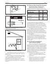
1. Main power: Connect a fused 120 volt supply
(15 amp) to the main power switch (see
Figure 20) (hot leg is connected directly to
switch). Neutral leg to white wire. Ground wire
can be connected to the grounding screw in the
box or on the switch.
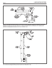
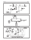
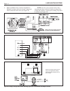
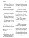
Figure 22. Multiple Zones Utilizing Four Wire Zone Valves with (Dry) End Switches.
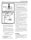
2. For single zone installations: (If external pump is
required, e.g., because of large system pressure
drop) connect room thermostat wires to the red
and white/red wires. Connect circulator (120
volt, 5 amps maximum) between the blue wire
and the white wire (neutral) (see Figure 21).
3. Zone Valves and Thermostats: Install external 24
volt transformer of sufficient V.A. to power
combined load of zone valves. Consult zone
valve manufacturer’s instructions. Connect
circulator (120 volt, 5 amp maximum) between
the blue wire and the white wire (neutral) (see
Figure 22).