


Endurance
Page 19
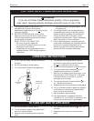
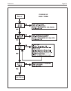
The appliance will attempt to ignite three times,
if ignition is not successful, the appliance will
lock out and display [LO]. Ignition reset is done
by pressing the reset button on top of the control
panel. EBP models will then operate to heat the
transfer tank.
7. EBP ONLY: Turn on a hot water tap. This puts
the appliance in the DHW mode.
Caution
Should any pronounced odor of gas be detected, or
if the gas burner does not appear to be functioning
in a normal manner, close main shutoff valve, do not
shut off switch, and contact your heating contractor,
gas company, or factory representative.
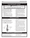
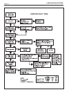
You MUST check flame monitoring control
(ignition system safety shut off device).
1. Close gas shutoff valve with burner operating.
2. The flame indicator light will go out and blower
will continue to run for the post purge cycle.
Three additional attempts to light will follow
including pre-purge, ignitor on, valve/flame on
and post purge. Ignition will not occur as the gas
is off. The display will eventually show [LO]
approximately 10 seconds after the gas valve has
closed on the third ignition attempt.
3. Open gas shutoff valve. Press reset button on the
top of the control panel. The ignition sequence
will start again and the burner will start. The
appliance will return to its previous mode of
operation.
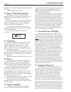
6D. Mode and On/Off Buttons Operation
The on/off button it is used to switch the
appliance from standby [ON] to standby [OFF] and
vice versa. It is NOT an isolation switch. The mode
button accesses all other functions as described in
their particular sections of this manual.
SECTION 7.
Maintenance and Component
Description
7A. Unit Pump
The unit pump operates whenever there is a call
for heat or hot water.
It is a wetted-rotor type pump and should always
be filled with water when it is operating so that it will
cool properly.
If a pump change is required for any reason,
valve off the boiler and drain approximately 1 or 2
gallons (approx. 4-8L) of water from it. Turn off the
main disconnect switch and unplug the pump wires,
remove the pump motor. The pump housing need not
be removed. The replacement pump motor should be
installed in the reverse order from which the old pump
motor was removed. After filling the system be sure
the combustion chamber coil vents through the air vent
located on top of the boiler chamber (inlet manifold
extension).
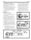
7B. Gas Valve
The gas valve is a 24VDC solenoid operated,
negative pressure regulated ratio valve. The outlet
pressure may be adjusted as described in the service
section. It is designed to operate with supply pressures
of 4-13 inches w.c. (1.0 to 3.2 kPa). To remove the gas
valve, shut off 120 volt power and the gas shutoff
valve, remove the 4 screws on the upper and lower
flanges and disconnect the wires from the gas valve,
the valve may now be removed. After the valve has
been removed, replace with a new valve in the reverse
order in which the old valve was removed. Turn on gas
shutoff valve and 120 volt power and check boiler
operation and gas tightness of gas valve connections.
7C. Safety Limit Switch
The Safety Limit Switch is an automatic reset
switch with a fixed set point of 230°F (110°C). To
replace the switch, shut off the 120 volt power.
Disconnect the 2 wires from the quick connects at the
switch and remove the switch. To replace, perform the
same operations in reverse. Turn on disconnect switch
and check boiler.
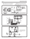
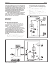
7D. Boiler Control Printed Circuit
Board (PCB)
The Integrated Boiler Control Module controls
the ignition process, the combustion process, the
temperature of the boiler flow and return, and the
transfer tank temperature* and provides both domestic
hot water* and space heating on demand.
To do this it takes inputs from three temperature
sensors, a domestic hot water flow switch, an overheat
thermostat (safety limit) and an external space heating
switch, such as a room thermostat, zone valve end
switches or circulator relay contacts. It then controls
the pump, blower, ignitor and gas valve sequencing.
It constantly displays the boiler outlet
temperature when the appliance is operating in one of
its demand modes. It also allows the user to obtain
information from the appliance to determine the water
temperature at three different locations within the
appliance and to find up to 8 previous faults stored in
memory.
If replacement of PCB is necessary, shut off the
120 volt power and disconnect the wire connectors
from the pcb. Remove the PCB from its location posts.