


Page 4
LAARS HEATING SYSTEMS
2. The CSA standard C22.1 “Canadian Electrical
Code - Part 1” and local codes.
All vent installations must be made in accordance with:
1. Part 7, Venting of Equipment of the National Fuel
Gas Code, ANSI 223.1 latest edition, or applicable
provisions of the local building codes or
2. CAN/CGA B149.
When required by the jurisdiction authority, the
installations must conform to the American Society of
Mechanical Engineers' Safety Code for Controls and
Safety Devices for Automatically Fired Boilers, No.
CSD-1.
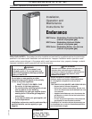
1C. Unpacking the Appliance
Remove all packing and tie down materials.
Make immediate claims (to the carrier) if the
appliance and its packaging are damaged.
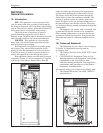
1D. Locating the Appliance
The appliance is designed for installation on
combustible flooring, in alcoves, basements, closets,
or utility rooms. It must not be installed on carpeting.
IF INSTALLED IN A FINISHED AREA,
PROVISION SHOULD BE MADE FOR DRAINAGE
OF ANY ACCIDENTAL SPILLAGE OR LEAKAGE.
The location for the unit should be chosen with
regard to venting dimensions, convenient access to
piping, and accessibility for service and cleaning.
The boiler shall be installed so that the gas
ignition system components are protected from water
(dripping, spraying, rain, etc.) during appliance
operation or service (circulator replacement, control
replacement, etc.).
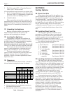
1E. Clearances
The dimension and criteria in Table 1 should be
followed when choosing the location for the unit.
SECTION 2.
Venting Options
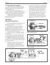
2A. Direct Vent Kits
When using a direct vent kit, the appliance is a
sealed combustion unit. All of its air is drawn in from
the outside through the 5" outer pipe. Flue gases are
vented through the 3" vent pipe positioned inside the
5" intake pipe. The hot flue gases are surrounded by
the intake flow of cooler outdoor air. This vent system
may be installed through, and be in contact with,
combustible materials. Except for roof vent kit (max 7'
vertical) all venting should pitch away (down) from
unit.
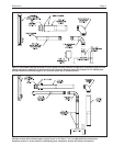
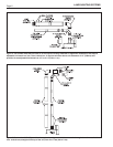
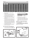
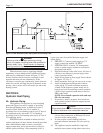
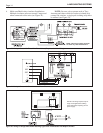
2B. Installing Direct Vent Kits
The direct vent appliance is certified with a
maximum of 15 linear feet (4.6m) of vent pipe and
three sets of elbows. There are two basic vent kits
available, together with various additional elbow and
extension kits if required (see Figures 3 and 4).
Detailed installation instructions are provided in the kits.
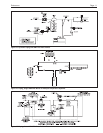
For additional length and/or fittings, the
following components are available:
3" and 5" elbow set Part Number 2400-330
5" x 1' extensions Part Number 2400-332
5" x 2' extensions Part Number 2400-334
5" x 2' to 4' adjustable
extensions Part Number 2400-336
3" x 1' extensions Part Number 2400-338
3" x 2' extensions Part Number 2400-340
3" x 2' to 4' adjustable
extensions Part Number 2400-342
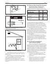
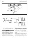
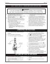
2C. Locating the Vent on an Outside Wall
The center line of the vent opening must be at
least 16½" (419mm) above grade, outside, and at least
13½" (343mm) from any other building opening, such
as doors, windows, etc. Vent opening should be well
away from shrubbery or other obstructions that would
prevent free air flow to and from vent terminal. Do not
terminate vent under decks, stairways, or car ports.
NOTE: Should it be impossible to locate
opening center line 16½" (419mm) above grade, use
optional vent terminal extension (p/n 2400-278).
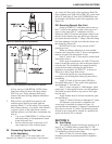
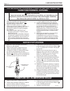
Vent terminals must also be at least 3' (0.9m)
above any forced air inlet located within 10' (3.0m),
and at least 7' (2.1m) above grade when located
adjacent to a public walkway, and cannot terminate in
a location where condensate or vapor may be a
nuisance, hazard, or could be a detriment to other
equipment. Vent terminals must have a minimum
clearance of 4' (1.2m) (6' (1.8m) in Canada)
horizontally from, and in no case above or below
electrical meters, gas meters, regulators, and relief
equipment unless a 4' (1.2m) horizontal distance is
maintained.
A. Minimum clearance from combustible construction to
meet AGA/CGA requirements.
B. Recommended clearance for accessibility and venting.
Table 1. Clearances
A B
AGA/CGA AGA CGA
in.
mm
in.
mm
in.
mm
Left Side 1 25 6 152 24 610
Right Side 1 25 12 305 24 610
Top Side 1 25 14 356 24 406
Back 1 25 9 229 12 305
Front 1 25 24 610 24 610
Vent: Direct Vent 0 0 0 0
Vent: Category IV 3 76 3 76